


62 Chapter 3
Overview of the Test Set’s Built-In Tools
Using RF Tools Program
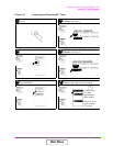
Cable Fault
NOTE Test Signal Can Cause Interference
When testing cables attached to antennas, test signals will be radiated.
Verify that the signal used for the test cannot result in interference to
another antenna.
This test operates over a wide frequency band. The test will always
operate with a center frequency of 505 MHz. The frequency span
however will be determined by the length of the cable measured. Longer
cables will use a narrower frequency span. The frequency span equals
990 MHz for cables less than 50 feet long and gets narrower as the
cable length increases. It is always safe to assume that the frequency
span is less than or equal to 990 MHz.
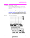
This test displays the return loss of a transmission line as a function of
the distance down the line. A frequency-swept signal from the DUPLEX
OUT port is applied through a resistive power divider to the
cable-under-test. Signals reflected from faults in the cable are combined
with the DUPLEX OUT signal in the power divider and applied to the
ANT IN port. The changing interference of the forward and reflected
signals, over the swept frequency band, contains information about the
distance to one or more faults. The software uses a Fast Fourier
Transform (FFT) to convert the frequency domain into the distance
domain. The distance displayed on the Test Set’s CRT is the physical
distance to the fault with correction for the velocity factor of the cable.
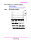
Cable Fault Performance
Measurements of the cable fault location can typically be made up to
500 feet on low-loss cables and 300 feet on higher-loss cables.
Resolution of the fault location is approximately 0.4 feet for cable
lengths up to 50 feet and then linearly increases to 4 feet for a 500 foot
cable.
Main Menu