


be taken not to puncture the inter
ior
walls or remove paint from the w
alls
during this procedure.
Be sure to disconnect power from
the
cabinet prior to starting
defrost
operation. After the cabinet is co
mpletely
defrosted, wash thoroughly,
remove
defrost water (Hussmann dipping
cases
are provided with an outside
drain
located on the operator’s side of the
case
base to assist you in this operation), w
ipe
the interior dry, and turn the power
back
on.
Be sure to allow the cabinet to cool dow
n
to its operating temperature
before
reloading.
CONDENSING UNIT
–
The condensing unit is mounted on
a
slideout base, accessible by removing
the
rear serving side access panel.
The
condenser is of the baretube design.
The
condenser fan motor draws the
air
through the rear access panel, across
the
compressor and discharges back out
the
rear access panel unless the case has
been
Field converted to front air discharge
as
previously discussed in the
Location
section of this manual.
For this reason, if
the case is installed in a counter, provisions
must be made for the release of the
discharge air.
CLEANING THE CONDENSER –
To clean condenser, a soft, nylon
brush
should be used to loosen dirt and
lint.
Then vacuum up the dirt or
blow
condenser out with a high-pressure
gas
such as nitrogen. Never use a wire
brush
to clean condenser tubes.
CLEANING EXTERIOR / INTERIOR –
When cleaning the exterior of the
cabinet
use a soft cloth or sponge with water
and
mild detergent. Rinse and wipe dry.
For cleaning the interior of the
product
compartment, a built-in drain has
been
provided with a standard hose
fitting
located at the front of the cabinet in
the
base area. Disconnect the
electrical
power and allow cabinet to warm
to
above freezing temperature. Use a
soft
cloth or sponge with a mild detergent
to
wash the interior. Wipe dry
before
restarting the cabinet. Allow the
cabinet
to cool down to proper
temperature
before reloadin g produc t.
SERIAL PLATE LOC ATION
–
One serial plate is located on the interio
r
left wall of the cabinet, and a second
one
in the condensing unit
compartment.
Both contain all pertinent infor
mation
such as model, serial number,
amperage
rating, refrigerant type and charge,
etc.
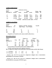
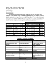
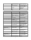
Specific charges are DCSG/DCCG-4
16
oz.,DCSG/DCCG-8 29 oz., DCSG/DCCG-
12 33 oz., and DCSG/DCCG-16 has
31
oz., all have R-404a. The “D”
models
have the same charge.
TEMPERATURE CONTROL
REPLACEMENT –
The Ranco temperature control is
located
in the compressor compartment.
To
replace, first disconnect power supply
and
remove two screws holding control
dial
plate. Pull capillary tube from
control
well, noting length of tube removed.
Push
new cap tube into well, being careful
not
to kink it, and making certain it
reaches
full depth of well.
7