


197
LZT 123 7263 R1C
12. Interface
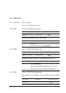
12.1 AT+CPIN PIN Control
See 3.26, AT+CPIN PIN Control
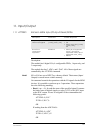
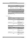
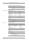
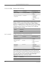
12.2 AT&C Circuit 109 (DCD) Control
Determines the behaviour of the carrier detect.
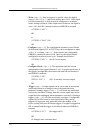
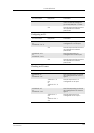
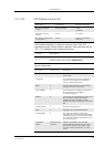
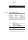
12.3 AT&D Circuit 108 (DTR) Response
Controls all actions initiated by data terminal ready from DTE.
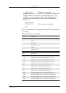
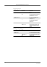
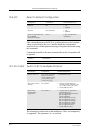
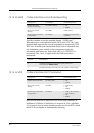
12.4 AT&S Circuit 107 (DSR) Response
This command is not availalbe in software releases up to and including
R2A.
Description Command Possible Responses
Set behavior of carrier
detect
AT&C[<value>] OK
ERROR
<value> Description
0 DCD always on
1 DCD follows the connection. Default value
Description Command Possible Responses
Control actions from
DTE
AT&D[<value>] OK
ERROR
<value> Description
0 Ignore. Default value
1 When in on-line data mode, switch to on-line command
mode. For all other states, see <value>=2
2 Disconnect and switch to off-line command mode
Description Command Possible Responses
Set behaviour of data
set ready
AT&S[<value>] •OK
•ERROR