


2. USING THE DEVELOPER’S KIT
35
LZT 123 7263 R1C
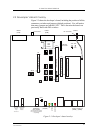
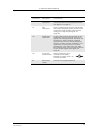
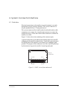
J10 SYSTEM
connector
For optional flat cable connection between
the module and the development board
(see Figure 2.3, page 31)
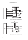
J11 TEST
connector
60 pin, 2.54mm pitch, dual row pin header
that carries all signals present at the system
connector of the module. Used for easy
testing of the signals (see Figure 2.4,
page 36)
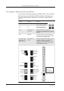
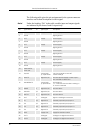
J12 Application
connector
For flat cable connection between a host
application and the module. Most of the
signals pass through jumpers that allow the
developer to select whether a specific
signal is routed to/from the development
board or to/from the host application. If no
application is connected to J12, these
jumpers (SW1, SW3, SW5, SW6, SW7, SW8,
SW9, SW10 & SW11) serve as on/off switches
for the module signals (see Figure 2.3,
page 31)
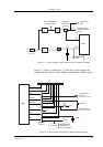
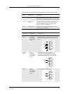
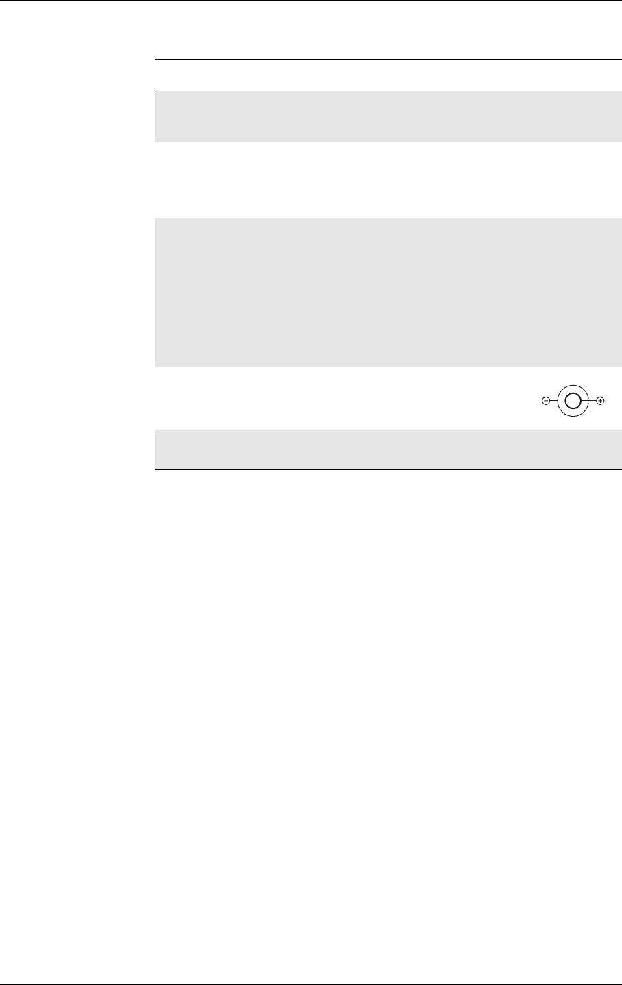
12v 2.1mm DC
Power Socket
Allows connection of an
external power supply.
Between 10V and 15V d.c. at
6 watts is required
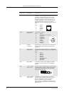
RF SMA panel
socket
Connect the supplied antenna
Connector Description Connections