


GM47/GM48 INTEGRATOR’S MANUAL
46
LZT 123 7263 R1C
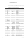
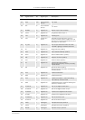
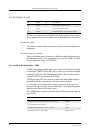
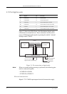
The electrical characteristics for VCC are shown in the table below.
Note! GM47 has no internal capacitance to supply the large current peaks
during GSM burst transmission. We recommend you follow these
general guidelines:
• Fit a low ESR electrolytic capacitor close to the module:
> 1,000µF;
<100mΩ ESR.
• Make sure power supply to module line resistance is <200mΩ.
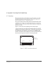
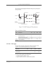
2.5 ON/OFF and External Power Signal
2.5.1 Switching the module ON and OFF
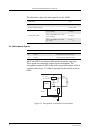
The module is turned on and off by momentarily grounding the
ON/OFF pin. This input should be driven by an open collector, or other
device which will not tie the input high, to allow the internal alarm clock
function to operate. See the table below for exact characteristics. In the
OFF state the current consumption of the module is less than 100µA.
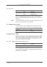
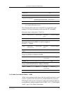
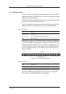
The ON/OFF signal is a digital input with the following characteristics:
Parameter Mode Limit
Vcc supply voltage
Nominal 3.6V
Tolerance
including ripple
a
a. Measured at system connector pins.
3.4V - 4.0V
Over-voltage limit 5.5V
Maximum ripple TBD
Maximum allowable voltage
drop
Burst transmission 200mV
Current drawn, at full TX
power
<350mA (average)
<2A (peak)
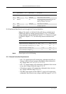
Pin Signal Dir Description
14 ON/OFF I Pulse signal to turn the module on or off
34 VIO O 2.75V supplied by the module
Parameter Min. Typ. Max. Units
Voltage HIGH level (FALSE) VCC V
Voltage LOW level (TRUE) 0 0.3 x VCC V
Pull-up resistance (internal) 39 kΩ