


GM47/GM48 INTEGRATOR’S MANUAL
62
LZT 123 7263 R1C
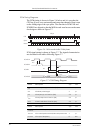
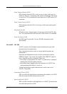
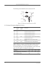
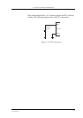
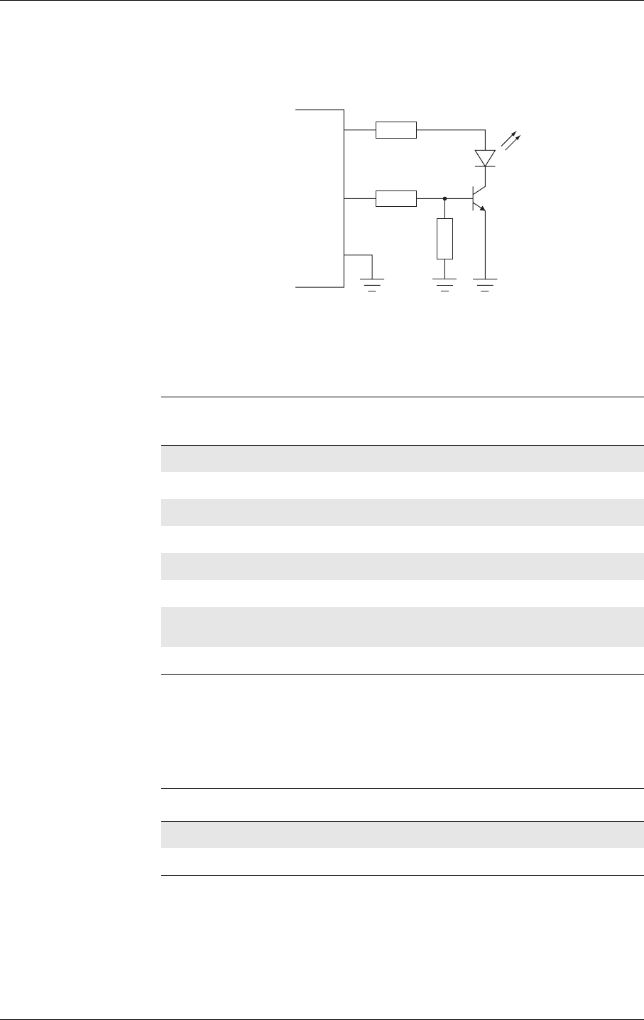
The following circuit should be used to connect an LED.
Figure 2.8 Electrical connections for the LED
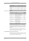
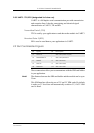
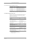
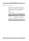
2.13 General Purpose Digital I/O Ports
Signals which have an entry in the Default Signal column in the above
table are multiplexed. Their operation depends on AT commands.
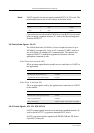
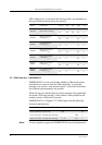
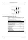
The following table gives you the input impedance. These values only
apply when the signals are configured as input signals.
VIO
LED
2k2
220
10k
BC817
GM47
DGND
Pin I/O port
signal
Default
signal
Description
21 IO1 - Programmable Input/Output 1
22 IO2 - Programmable Input/Output 2
23 IO3 - Programmable Input/Output 3
24 IO4 - Programmable Input/Output 4
37 IN5 DTR Programmable input 5/Data Terminal Ready
32 OUT5 - Programmable output 5
36 OUT6 RI Programmable Output 6/Data Carrier
Detect
38 OUT7 DCD Programmable Output 7/Ring indicator
Parameter Min. Typ. Max. Units
Input impedance (IO1 - IO4) (pull-up) 20 39 100 kΩ
Input impedance (IN5) 100 kΩ