


2. SYSTEM CONNECTOR INTERFACE
65
LZT 123 7263 R1C
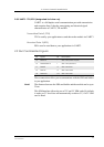
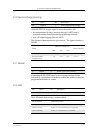
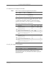
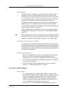
2.15 External I
2
C Serial Control Bus
Note! The I
2
C bus is currently not supported by the software
The external I
2
C bus consists of two signals, SDA and SCL. This bus
is isolated from the module’s internal I
2
C bus to ensure proper
operation of the module, even if the external I
2
C bus is damaged.
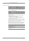
The electrical characteristics are shown below.
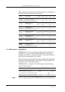
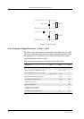
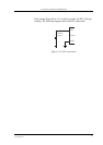
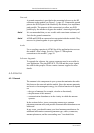
2.16 TX_ON - Burst Transmission
Burst transmission is the time when a GSM transceiver unit is
transmitting RF signals. TX_ON indicates the module is going into
transmission mode.
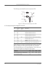
Pin Signal Dir Description
29 SDA I/O
I
2
C serial data
30 SCL O
I
2
C serial clock
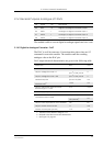
Parameter Min. Typ. Max. Units
Transmit
operation
Frequency I
2
C CLK
81.25 400 kHz
High or low I
2
C CLK
1.2 µs
Delay time after falling edge of I
2
C
CLK
308 308-
1230
ns
Hold time after falling edge of I
2
C
CLK
0 ns
Receive
operation
Frequency I
2
C CLK
400 kHz
High or low I
2
C CLK
1.2 µs
Delay time after falling edge of I
2
C
CLK
100 ns
Hold time after falling edge of I
2
C
CLK
0 ns
Pin Signal Dir Description
35 TX_ON O GSM module to transmit