


4. HINTS FOR INTEGRATING THE MODULE
73
LZT 123 7263 R1C
determine whether the antenna needs to be grounded or not. Your local
antenna manufacturer might be able to design a special antenna suitable
for your the application.
4.3.2 Antenna Type
Make sure that you choose the right type of antenna for the module.
Consider the following requirements:
• the antenna must be designed for the dual frequency bands in use:
EGSM/GSM900/1800 for the GM47 and
GSM850/1900 for the GM48;
• the impedance of the antenna and antenna cable must be 50Ω;
• the antenna output-power handling must be a minimum of 2W;
• the VSWR value should be less than 3:1 to avoid damage to the
module.
4.3.3 Antenna Placement
The antenna should be placed away from electronic devices or other
antennas. The recommended minimum distance between adjacent
antennas, operating in a similar radio frequency band, is at least 50cm.
If signal strength is weak, it is useful to face a directional antenna at the
closest radio base station. This can increase the strength of the signal
received by the module.
The module’s peak output power can reach 2W. RF field strength varies
with antenna type and distance. At 10cm from the antenna the field
strength may be up to 70V/m and at 1m it will have reduced to 7V/m.
In general, CE-marked products for residential and commercial areas,
and light industry can withstand a minimum of 3V/m.
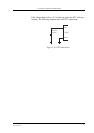
4.3.4 The Antenna Cable
Use 50Ω impedance low-loss cable and high-quality 50Ω impedance
connectors (frequency range up to 2GHz) to avoid RF losses. Ensure
that the antenna cable is as short as possible.
The Voltage Standing-Wave Ratio (VSWR) may depend on the
effectiveness of the antenna, cable and connectors. In addition, if you
use an adapter between the antenna cable and the antenna connector, it
is crucial that the antenna cable is a high-quality, low-loss cable.
Minimize the use of extension cables, connectors and adapters. Each
additional cable, connector or adapter causes a loss of signal power.