


1. INTRODUCTION
27
LZT 123 7263 R1C
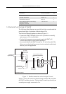
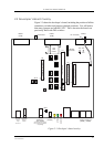
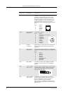
Figure 1.2 Power supply connection and the on-board voltages
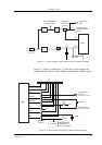
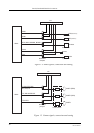
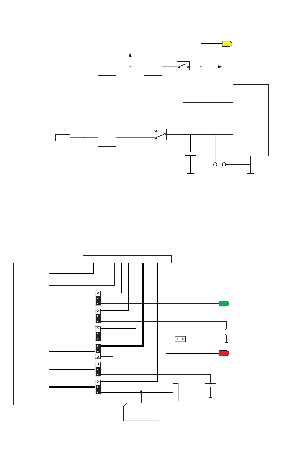
Figure 1.3, Figure 1.4 and Figure 1.5 show how various signals are
routed on the developer’s board. Thicker lines indicate multiple signals.
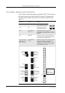
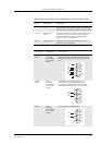
Figure 1.3 Miscellaneous signals, connection and routing
GM47
Vcc
DC Power Socket,
Input 10..15V
5V
reg.
2V7
reg.
5V to development
board circuits
To development
board & interface
circuits
VIO
VCC
VIO present
LED
+-
TP4 TP5
3V8
Switched
when VIO
present
3V8
reg.
2V7
12v
J12
GM47
STATUS LED
(Blinks when
connected to network)
ON/OFF
Selectable
Jumpers
n/c
J5
U10 SIM
SIM holder with
SIM presence
switch (to DGND)
0.22F
SIM
VRTC
I²C
SERVICE
ON/OFF
LED
General purpose I/O
VIO
SW4
2V7
SERVICE LED
(Lit when SW4 closed)