


GM47/GM48 INTEGRATOR’S MANUAL
32
LZT 123 7263 R1C
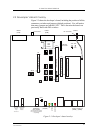
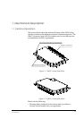
2.3 Jumpers, Switches and Connectors
You will notice that many jumpers are labelled “SW”. This is because
the board was previously fitted with DIL switches. All jumpers are
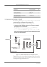
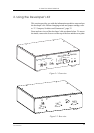
located on the developer’s board (see “Developer’s board overlay”,
page 31).
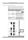
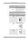
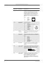
Jumper Signal Setting
JP18 TD Maintain jumper in
lower default position
JP21 RD Maintain jumper in
lower default position
JP24 Reserved for
future use
MUST remain open to prevent
damage to the module. As an extra
precaution, maintain DCIO in the OFF
position
SW4 SERVICE Connect the pins using the floating
connector ONLY when programming
the module or logging data
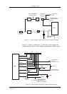
SW1, SW3, SW5,
SW6, SW7, SW8,
SW9, SW10,
SW11, J11 links
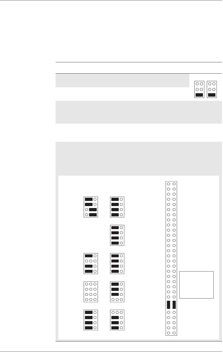
See diagram
below
Default positions shown below. Move
any “SW” jumper to the right-hand
position to divert the signal to
connector J12. Remove the J11 links
to bypass J8, J9 or CP1 and process
audio signals externally
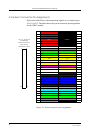
JP21 JP18
SIMRST
SIMCLK
SCL
SDA
SW8 SW1
ON/OFF
PRESENCE
SIMVCC
SIMDAT
SW9
BUZZER
LED
RI
DCD
VRTC
RD3 (RX3)
TD3 (TX3)
SW11 SW6
DTR
CTS
RTS
RD (DFMS)
PCMULD
PCMIN
PCMOUT
PCMCLK
SW7 SW3
TD (DTMS)
RD2 (CFMS)
TD2 (CTMS)
PCMDLD
BEARP
SERVICE
AFMS
ATMS
SW10 SW5
PCMSYN
MICN
MICP
BEARN
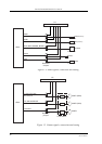
J11
59 60
50
4847
49
The links shown
on J11 must be
in place to
access audio
on J8, J9 or CP1