


41
LZT 123 7263 R1C
2. System Connector Interface
2.1 Overview
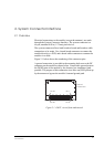
Electrical connections to the module (except the antenna), are made
through the System Connector Interface. The system connector is a
60-pin, standard 0.05in (1.27mm) pitch device.
The system connector allows both board-to-board and board-to-cable
connections to be made. Use a board-board connector to connect the
module directly to a PCB, and a board-cable connector to connect the
module via a cable.
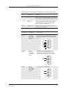
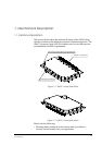
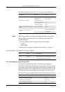
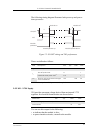
Figure 2.1 below shows the numbering of the connector pins.
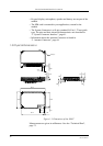
A ground connection is provided at the mounting hole next to the RF
connector on the module as shown below. Connect this ground point to
the DGND pins of the module by the shortest, low-impedance path
possible. The purpose of this connection is to allow any ESD picked up
by the antenna to bypass the module’s internal ground path.
Figure 2.1 GM47, viewed from underneath
Pin 59 Pin 1
Pin 60 Pin 2
Ground
connection