


GM47/GM48 INTEGRATOR’S MANUAL
44
LZT 123 7263 R1C
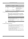
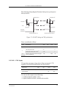
2.2 General Electrical and Logical Characteristics
Many of the signals, as indicated in the table above, are high-speed
CMOS logic inputs or outputs powered from a 2.75V±5% internal
voltage regulator, and are defined as Digital 2.75V. Whenever a signal
is defined as Digital 2.75V, the following electrical characteristics
apply.
Note! Unused pins can be left floating.
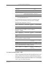
2.2.1 General Protection Requirements
• All 2.75V digital inputs will continuously withstand and suffer no
damage in the power-on or power-off condition when subjected to
any voltage from -0.5V to 3.47V (3.3V+5%).
• All 2.75V digital outputs will continuously withstand a short circuit
to any other voltage within the range 0V to 3V.
• All analogue outputs will continuously withstand a short circuit to
any voltage within the range 0V to 3V.
• The SIM output signals and the SIMVCC supply will continuously
withstand a short circuit to any voltage within the range 0V to 5.8V.
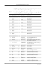
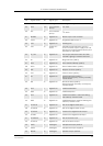
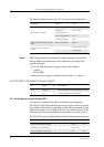
56 BEARN O Analogue Speaker output negative
57 AFMS O Analogue Audio output from module
58 SERVICE I 2.7V Flash programming voltage for the MS.
Enable logger information if not
flashing. Formerly VPPFLASH
59 ATMS I Analogue Audio input to module
60 AGND - - Analogue ground
Pin Signal Name Dir Signal Type Description
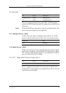
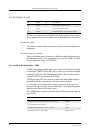
Parameter Min. Max. Units
High Level Output Voltage (V
OH
), I
o
= –2mA 2.2 2.75 V
Low Level Output Voltage (V
OL
), I
o
= 2mA 0 0.6 V
High Level Input Voltage (V
IH
) 1.93 2.75 V
Low Level Input voltage (V
IL
) 0 0.8 V