


GM47/GM48 INTEGRATOR’S MANUAL
50
LZT 123 7263 R1C
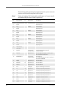
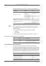
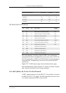
The table below shows the audio signal levels for AFMS.
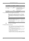
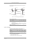
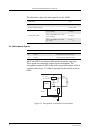
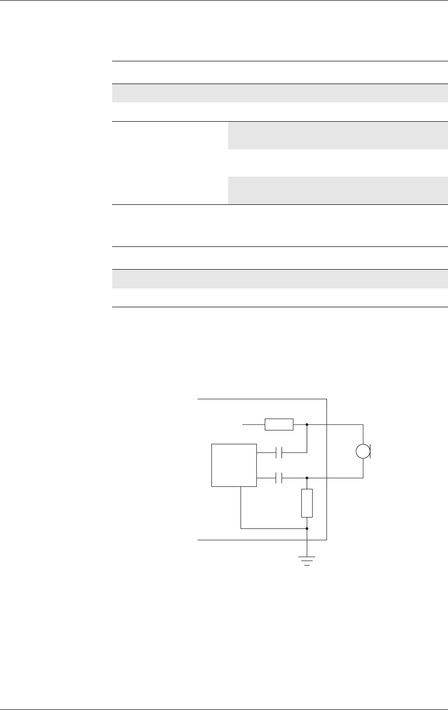
2.6.3 Microphone Signals
MICP and MICN are balanced differential microphone input pins.
These inputs are compatible with an electret microphone. The
microphone contains an FET buffer with an open drain output, which is
supplied with at least +2V relative to ground by the module as shown
below.
Figure 2.3 Microphone connections to the module
Parameter Limit
Speaker impedance 64Ω to 1kΩ
Output Capacitance 2.2µF ±10%
Levels (THD <5%)
Drive capability into 5kΩ
(0.3 - 3.5kHz)
>2.4V
p-p
Drive capability into 1.5kΩ
(0.3 - 3.5kHz)
>2.2V
p-p
Drive capability into 150Ω
(at 1kHz)
>1.3V
p-p
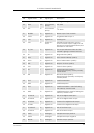
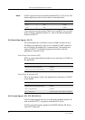
Pin Speaker signals Dir Function
53 MICP I Microphone positive input
54 MICN I Microphone negative input
MICP
1k
1k
GM47
MICN
68nF
68nF
2 - 2.5V
@ 1mA
CODEC
AGND