


GTR64 http://www.matrix.es/GTR64
3. ELECTRICAL DESCRIPTION
All electrical connections to the module are protected in compliance with the standard air and contact
Electrostatic Discharge (ESD).
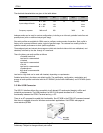
The module uses the following industry standard connectors:
• Sub-D 9 pin female (Main RS232 serial port)
• High density 15 pin (Secondary RS232 UART and extended I/O interface)
• RJ12 6-way (power supply connector)
• RJ9 4-way (handset connector)
• SIM card reader
• FME male coaxial jack (antenna connector)
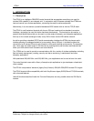
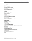
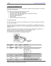
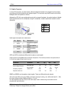
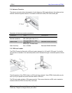
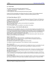
3.1 Power Conector
An RJ11 6-way connector, as shown and described below, serves means of supplying and controlling
d.c. power to the modem.
The supply voltage, VCC, required by the modem is in the range 32V d.c. Application of the supply
voltage does not switch the modem on. To do so an additional active-high control signal, TO_IN, must
applied for > 0.2s.
A second active-high control signal, HR_IN, can be used to switch modem off when applied for 1 - 2
seconds, or can be used to perform hardware reset when applied for > 3.5s.
TO_IN and HR_IN are referenced to GND (pin 6 on the connector).
VCC and GND are reverse polarity and overvoltage protected.
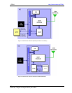
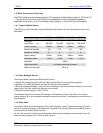
PIN: Signal Dir Limits Description
1 VCC Input 5-32 V DC Positive power input
2 VCHARGE Input
3 HR_IN Input 5 – 36 V
Active high control line used to switch off or
reset the modem
VIH > 5V, VIL < 2V
Power off: 1s < t < 2s
Hard reset: t > 3.5s
4 TO_IN Input
5 – 36 V
Active high control line used to switch on the
modem
VIH > 5V, VIL < 2V
Power on: t > 0.2s
5 3.6V out Output 3.6V DC reference signal output. Max 75mA
6 GND Input
Negative power (ground) input and return
path for TO_IN, HR_IN and VCHARGE
GTR64 Integrators Manual V.1.2 Pag. 13
Preliminary. Subject to change without prior notice