


GTR64 http://www.matrix.es/GTR64
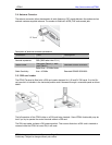
3.2 Audio Conector
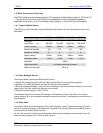
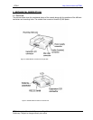
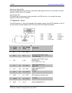
4-way RJ9 connector, as shown below, allows a telephone handset to be plugged into the modem,
iving access to the microphone and earpiece signals. The connector may also be used to drive other
nalogue audio sub-systems or devices.
lthough the GTR-64 is pre-configured to work with a range of handsets, the audio interface is flexible
nd its performance can be configured, using AT commands, to match a particular handset or audio
bsystem.
udio sig
A
g
a
A
a
su
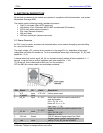
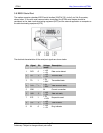
1 MICN
2 BEARN
3 BEARP
4 MICP
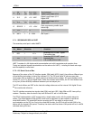
A nal descriptions are listed below:
Pin Signal Dir Description
1 MICN I
Microphone negative
input
2 BEARN O
Earpiece negative
output
3 BEARP O
Earpiece positive
output
4 MICP I
Microphone positive
input
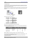
MICP and MICN are balan diffe ut signals.
These inputs tib ith one.
The terminal provides a microphone bias at
2.4V, an n least 1mA o
BEARP and BEARN are the speaker output signals. These are differential-mode outputs.
With a full-scale PCM input to the CODEC, 0 dB audio output gain setting, and a differential load RL = 30Ω,
the output voltage between EARP and EARN is 1.5 V rms.
For load resistances less than 30Ω, the full-scale output needs is limited using the modules internal
programmable gain attenuator.
ced rential microphone inp
are compa
supply at
le w an electret microph
f current.d ca
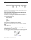
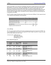
Parameter Conditions Min Typ Max Unit
max input gain 14 16 18 mVrms
Input voltage full scale
50 56 mVrms
Frequency response -3dB cut-off 300 3400 Hz
min input gain 45
Output dc bias level 2.16 2.4 2.64 V
GTR64 Integrators Manual V.1.2 Pag. 14
Preliminary. Subject to change without prior notice