


GTR64 http://www.matrix.es/GTR64
3.6.1 Serial Data
The modem su ts t er
• 1 start bit, 7 or 8 data bits, 1 optiona it, 1 or 2 stop bits
• Programmable baud rate
• Auto-configur n m ith to-b ut
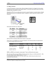
In line with ser om atio rm e ta circuit-terminating equipment
(DCE) and the external application or computer is the data terminating equipment (DTE).
.6.2 Serial Data Signals - RD, TD
he default baud rate of the UARTs is auto-baud. Baud rates of between 600 bauds to 460 kbauds are
ossible. The wireless modem also supports 3GPP TS 27.010 multiplexing protocol, which starts when
mand is sent.
dem (RD)
application.
odem.
of
e flow control
not used in communications between the application and the wireless modem, some applications may
o each other at the wireless modem. Users should familiarize
ation of their UART.
are control can be
is ready for communication.
R line can al sed to switch on the modem when activated for 0.2 seconds. The DTR line
) correctly.
onfirm that a communications
and AT&S.
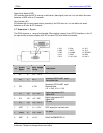
ppor the standard da a charact format of
l parity b
atio ode w au aud and a o-format operation
ial c munic n te inology th module is the da
3
T
p
the appropriate com
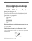
Serial Data From Mo
RD is an output signal that the modem uses to send data to the
Serial Data To Modem (TD)
TD is an input signal, used by the application to send data to the m
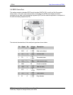
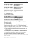
3.6.3 Control Signals - RTS, CTS, DTR, DSR, DCD, RI
Depending upon the user application, some, all, or none of the control signals may be needed. Each
he control signals can alternatively be configured as a general purpose IO. When hardwar
t
is
require RTS and CTS to be connected t
hemselves with the specific implement
t
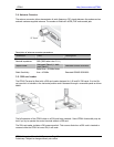
RTS and CTS are capable of transmitting at 1/10th of the data transmission speed for data rates up to
460kbps (byte-oriented flow control mechanism).
Request to Send (RTS)
Used to condition the DCE for data transmission. The default level is high by internal pull up.
The exact behaviour of RTS is defined by an AT command. Software or hardw
selected. Hardware flow is the default control.
The application must pull RTS low to communicate with the modem.
The modem will respond by asserting CTS low, indicating it
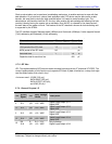
Clear To Send (CTS)
CTS indicates that the DCE is ready to transmit data. The default level is high. You can define the exact
behaviour of CTS through an AT command, and can select software or hardware flow control.
Data Terminal Ready (DTR)
DTR indicates that the DTE is ready to transmit and receive data. It also acts as a hardware ‘hang-up’,
terminating calls when switched high.The signal is active low. You can define the exact behaviour of
DTR with an AT command.
The DT so be u
must be deactivated prior to swi
tching off the modem to ensure it switches off (powers down
Data Set Ready (DSR)
An active DSR signal is sent from the modem to the application (DTE) to c
path has been established. DSR has two modes of operation, settable using the AT comm
GTR64 Integrators Manual V.1.2 Pag. 18
Preliminary. Subject to change without prior notice