


GTR64 http://www.matrix.es/GTR64
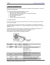
Data Carrier Detect (DCD)
DCD indicates that the DCE is receiving a valid carrier (data signal) when low. You can define the exact
behaviour of DCD with an AT command.
Ring Indicator (RI)
RI indicates that a ringing signal is being received by the DCE when low. You can define the exact
behaviour or RI with an AT command.
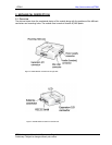
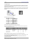
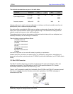
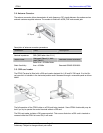
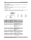
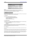
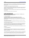
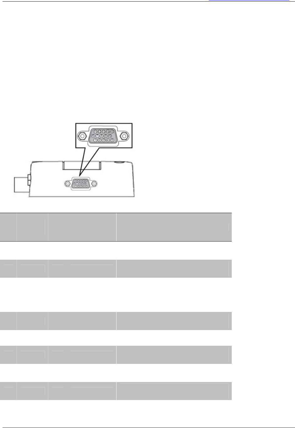
3.7 Expansion I/O port
The GTR64 supports a range of configurable I/Os including a second 2-wire RS232 interface. on the 15
together with I2C bus and VTRC with ALARM functionality.
pin high density connector
Pin
GTR64
Signal
Dir
Max. Voltage
limits
Description
1 SCL O -0.5 - +3.6 V
I2C clock sign
a
l
2 RD3 I ±5 v
Secondary RS232 UART signal:
Transmitted data
3 TD3 ± 25V
Secondary RS232 UART signal
Received data.
V IL < 0.6V, V IH > 2.4V
4 IO 1 I/O -0.5 - VREF
Digital input/output I/O 1
Digital VREF
5 I -
Digital input/output I/O 3
O 3 I/O 0.5 - VREF
Digital VREF
6 SDA I/O -0.5 - +3.6 V
I2C data
7 VRTC I 1,1 – 1,55 V for real time clock VRTC supply
8 ALARM O -0.5 - +3.6V
RTC Alarm
9 VREF O +3.6 V LEAVE UNCONNECTED !!!
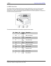
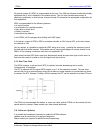
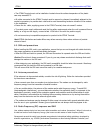
1. SCL 6. SDA 11. IO 2
2. RD3 7. VRTC 12. IO 4
ICE
5. IO 3 10. RI / IO8 15. ADC 1
3. TD3 8. ALARM 13. SERV
4. IO 1 9. VREF 14. GND
GTR64 Integrators Manual V.1.2 Pag. 19
Preliminary. Subject to change without prior notice