START UP
LOCATION
–
The location of your cabinet is
Make sure your selected location is
in any of the following areas as it cou
seriously affect the operation.
•
Not in direct sunlight.
•
Not in the air path of heat or air
conditioning ducts.
•
Not at an exit or entrance affected by
extreme temper ature change.
Allow 2 feet of clearance at the rear of
case to allow adequate air
across the condenser for
refrigeration system performance, do
obstruct the grille at the rear intake
discharge. If desired, the blank off
behind the front (customer side)
panel – may be removed for rear
intake and front air discharge, but
insure 2 feet of unobstructed clearance
left at the case front.
Level case front to back and end to
shimming where necessary
installation to assure proper op
drains, and refrigeration system.
equipment on the same circuit. Use
time delay fuse or circuit breaker.
supply circuit must be properly
and conform to National and
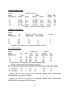
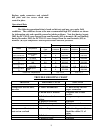
Electrical Codes. Voltage, as measured
the compressor terminals
operation, must not vary more than
from cabinet serial plate rating. If a
voltage condition exists, contact
electrician or power company.
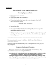
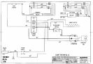
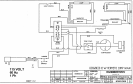
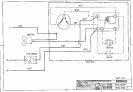
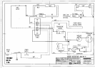
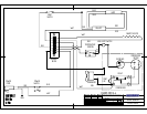
A wiring diagram is provided on the
condenser shroud for each unit.
A power (ON-OFF) switch is provided
each model. The switch is accessib
through a hole provided in the rear
(operator side) access panel
STAR T UP P ROCEDUR E
-
•
Cut the band which holds
compressor in place during shipment.
•
Make sure fan turns freely. Check
any connections or parts that
have loosened during shipment.
•
Start cabinet, and allow
to pull down to normal level
loading product.
The DC models are equipped with
three-wire grounded service core for
protection. The cabinets are designed
operate on 115V single-phase
current. A separate circuit
recommended to prevent product loss