


Installation
12/07 4905 Series Conductivity Cells – Installation and Maintenance 7
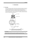
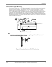
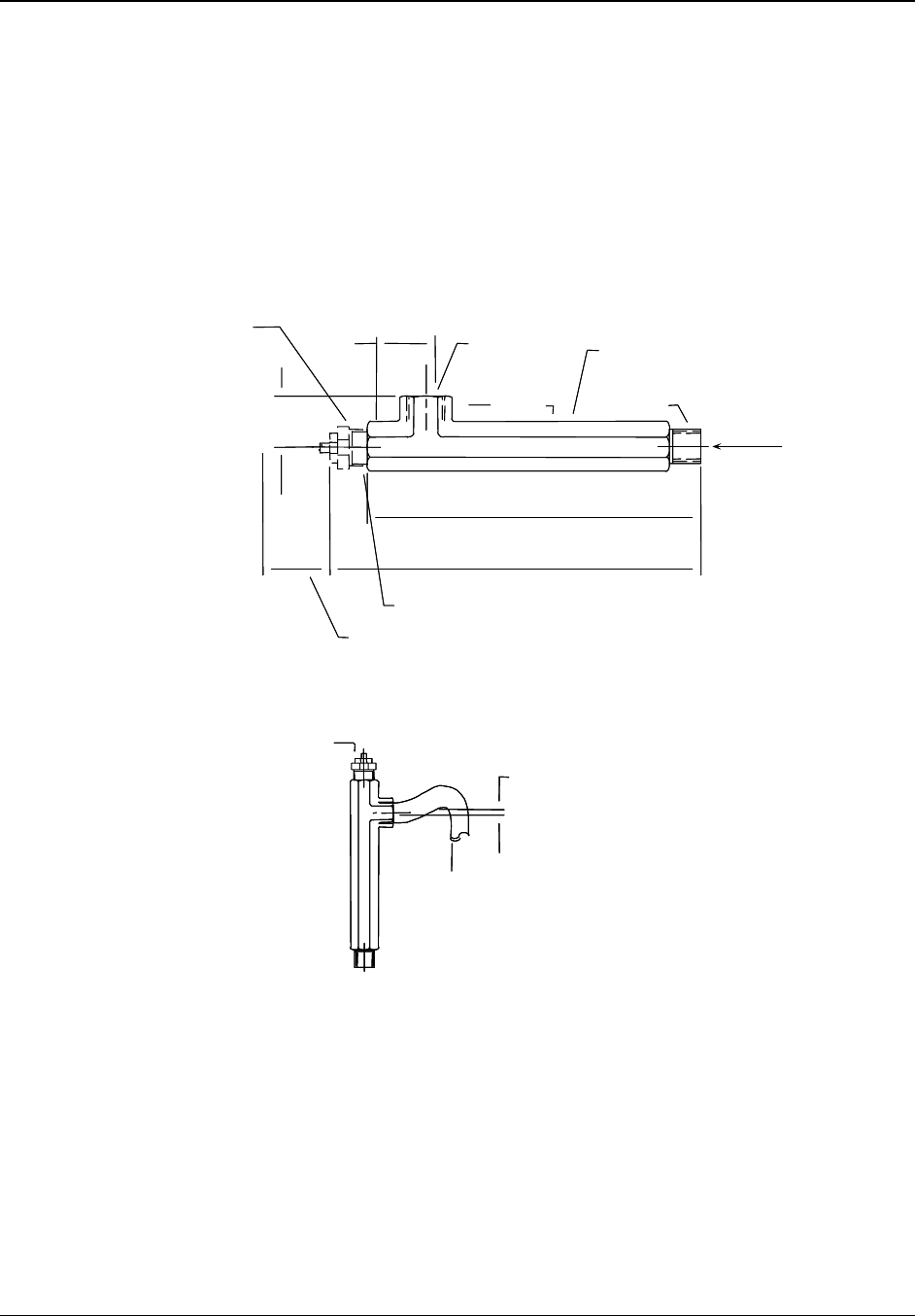
3.6 Insertion-Type Mounting
The cell can be inserted into a 1” N.P.T. threaded opening, but it is imperative that the tank or chamber be
full under all process conditions. Make certain the liquid head is above the cell location. A vertical
insertion (from above) or a horizontal insertion can be used. To install, simply tighten the cell into a 1”
N.P.T. threaded opening (using a Teflon thread compound such as Teflon tape) so that the entire electrode
is immersed in the measured solution. Allow at least 1/2-inch clearance beyond the end of the cell. In
applications where vertical mounting is required, avoid a position with the cell channels pointed up, as this
will permit solution to flow down into the open end of the cell and may result in clogging by solids settling
in the cell channels. See
Figure 3-1.
C
EL
L
I
N
11/2"
(38mm)
83/4"
(222 mm)
13 1/4"
(337mm)
1" Fit t ing
All ow 7 3/4" (197mm) for r emoval o
fcell
3/ 4" NPT
Fl ow I n
Flow Chamber
11/2"
(38mm)
Octa gon
3/ 4" NPT
Flo w Out
11/2"
(38mm)
11/2"
(38mm)
Octagon
2" mi n.
(51mm)
C
E
L
L
IN
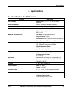
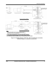
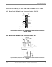
Notes
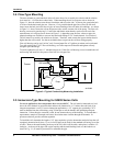
1. Mount cell and flow chamber horizontally as shown above with flow exit “up to eliminate possible air gap around cell body.
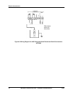
2. If cell and flow chamber must be mounted vertically, attach a short length of tubing to flow exit as shown below and form
a trap to ensure filing of flow chamber, especially at low flow.
C
EL
L
I
N
11/2"
(38mm)
83/4"
(222 mm)
13 1/4"
(337mm)
1" Fit t ing
All ow 7 3/4" (197mm) for removal o
fcell
3/ 4" NPT
Fl ow I n
Flow Chamber
11/2"
(38mm)
Octa gon
3/ 4" NPT
Flo w Out
11/2"
(38mm)
11/2"
(38mm)
Octagon
2" mi n.
(51mm)
C
E
L
L
IN
2" mi n.
(51mm)
C
E
L
L
IN
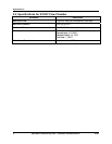
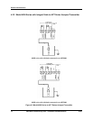
Notes
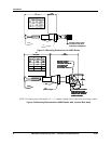
1. Mount cell and flow chamber horizontally as shown above with flow exit “up to eliminate possible air gap around cell body.
2. If cell and flow chamber must be mounted vertically, attach a short length of tubing to flow exit as shown below and form
a trap to ensure filing of flow chamber, especially at low flow.
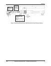
Figure 3-2 Dimension Drawing for 276127 Flow Housing