


2-4 A 8-bit 16-bit timer, a peripheral initial
2-4 A 8-bit 16-bit timer, a peripheral initial
2-4-1 The various registers of a 8-bit timer
Book LSI contains eight 8-bit timers, and is an interval timer, an event timer counter, and a clock output. It
can be used as the standard clock of a serial interface, and start timing of A/D conversion.
These timers can perform cascade connection use of a maximum of four.
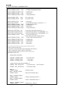
●Timer register
It is the 8-bit register which counts a timer. A count value can be read by the down counter.
TM0BC,TM1BC,TM3BC,TM4BC,TM5BC,TM6BC,TM7BC
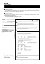
●Timer mode register
It is the 8-bit register which sets up the mode of a timer of operation.
The clock source which can be chosen by each timer is different. Be careful of a setup.
TM0D: Timer 0 mode register
Bit7 : Count operation permission
0: A stop of operation
1: Permission of operation
Bit6 : Base register setup
0: Usually, operation
1: Initialization
The value of a base register is loaded to a binary counter.
The timer pulse output 0 is reset on a low level.
Bit5-3: Prohibition (0 fixation)
Bit2-0: Clock source selection
000:IOCLK
001:IOCLK/8
010:IOCLK/32
011: Prohibition of a setup
100: Prohibition of a setup
101: Timer 1 underflow
2-30