


SAMSUNG Proprietary-Contents may change without notice
2-2. Baseband Circuit description of SGH-Z300
2-2-1. PM6650
- Power Management
Ten low-dropout regulators designed specifically for GSM applications power the terminal and help ensure optimal
system performance and long battery life. It provides LDOs support for 1.375V, 1.8V, 2.6V, 2.85V,
3.3V.
IC-level interfaces include the three-line serial bus interface(SBI) used by the MSM6250 device to control
and status the PM6650 IC.
- Keypad Backlight
The Keypad backlight driver output is at pin 23 (KYPD_BACKLIGHT_DRV) and is designed to drive parallel
connected LEDs directly. Its output current level is SBI-programmable and meets the performance specified below.
Input parameters are not specified since they are internal.
- TCXO Controller and Buffers
The PM6650 IC includes circuits for controlling the TCXO warm-up and buffering its signal for distribution
throughout the handset. Performance specifications are presented below.
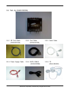
2-2-2. Connector
- LCD Connector
LCD is consisted of main LCD(color 262K TFT LCD) and small LCD(OLED color 65K LCD). Chip select signals
in the U300, MAIN_LCD_CS can enable main LCD and SUB_LCD_CS can enable small LCD. CAM_PWR_ON
signal enables white LED of main LCD. MAIN_LCD_RESET signal initiates the reset
process of the main LCD. SUB_LCD_RESET signal initiates the Reset process of the small LCD.
16-bit data lines(D2(0)~D(15)) transfers data and commands to LCD. Data and commands use "RS" signal.
If this signal is high, Inputs to LCD are commands. If it is low, Inputs to LCD are data. The signal which informs
the input or output state to LCD, is required. But this system is not necessary this signal.
Power signals for LCD are "VBATT_LCD". "SPKP_RCVP" and "SPKP_RCVN" from HEA401 are used for audio
speaker. And "MOTOR_EN" from U100 enables the motor.
- Key
This is consisted of key interface pins among U100, KEYSENSE_N(0:4). These signals compose the matrix.
Result of matrix informs the key status to key interface in the U100. Power on/off key is seperated from the
matrix. The key LED use the "VBATT" supply voltage. "KEY_LED" signal enables LEDs with current control.
"HALL_SW" informs the status of folder (open or closed) to the. This uses the hall effect IC, A3212ELH.