


Installation
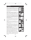
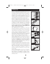
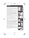
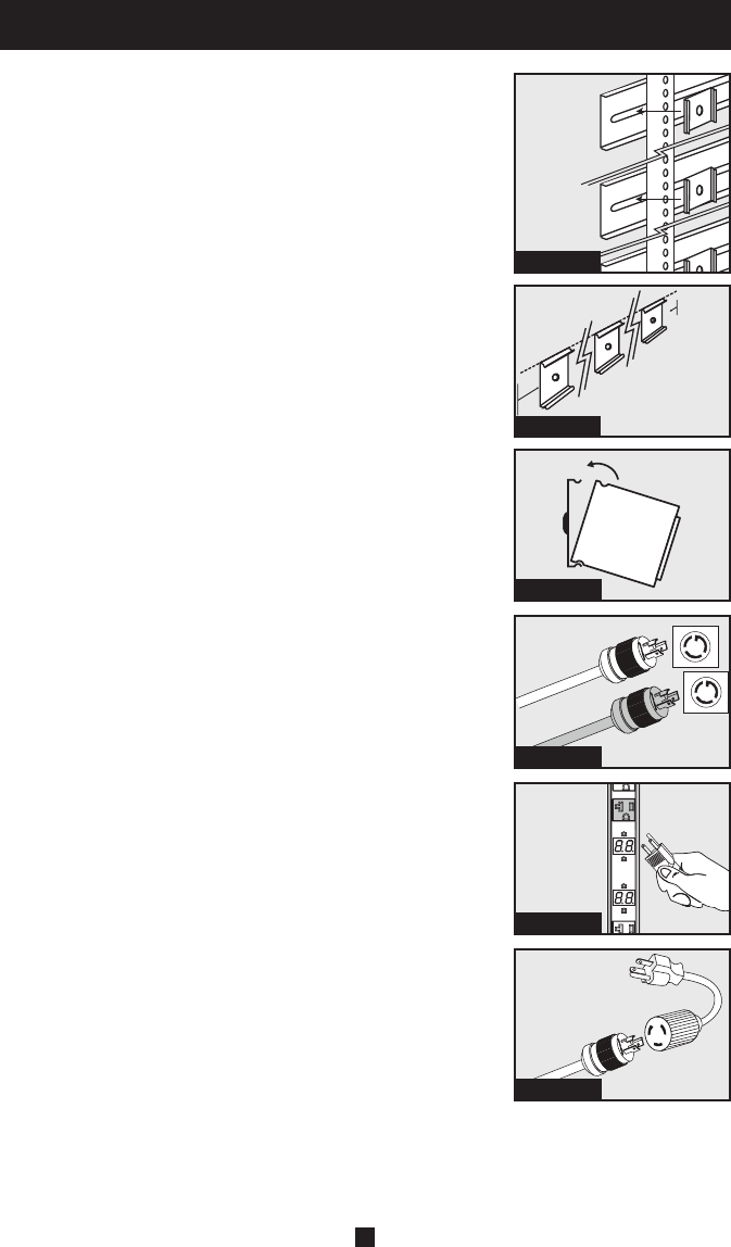
STEP 1A - Zero U Rack Configuration. Attach the three
mounting clips supplied with the PDU to the rack enclosure
using the included hardware. The mounting clips should be
attached along a vertical plane at equidistant points which
roughly correspond to the center and ends of the PDU. The
exact mounting configuration may vary depending on the rack
and enclosure. If possible, use pre-existing mounting points
within the enclosure.
STEP 1B - Wall or Under-Counter Configuration. Attach
the three mounting clips supplied with the PDU to a wall or
similar flat, secure surface using the included hardware. The
mounting clips should be attached along a vertical or
horizontal plane at equidistant points which roughly
correspond to the center and ends of the PDU. If possible, use
pre-existing mounting points. WARNING: Do not attempt
to mount the PDU with the outlets facing downward; the
mounting clips are not designed to support the weight of
the PDU in that manner.
Note: Regardless of configuration, the user must determine
the fitness of hardware and procedures before mounting. The
PDU and included hardware are designed for common rack
and rack enclosure types and may not be appropriate for all
applications.
STEP 2: Attach the PDU to the mounting clips. Using an
assistant, place a rear corner of the PDU at an inside edge of
the mounting clips, pivot the PDU toward the alternate inside
edge and snap into place.
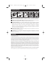
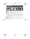
STEP 3: Attach each input plug of the PDU to a grounded
outlet. The input plugs, power cords, breakers and outlets are
color-coded to correspond to the two independent power
circuits. WARNING: Attach each input plug to a separate
power circuit. Consult with the electrician at the
installation site if necessary.
STEP 4: Attach equipment to the PDU. Do not exceed the
load rating for each circuit; distribute equipment appropriately
between the two circuits to obtain the maximum utility from
the PDU. The total electrical current used by each circuit will
be displayed on the corresponding digital meter in amperes.
The meter labels are color-coded to match the circuits.
STEP 5: Optional Installation. The PDU includes two
adapters that convert the L5-20P input plugs to 5-20P input
plugs. Use both adapters, a single adapter or neither of the
adapters. The adapters are optional; the PDU will work
properly without connecting the adapters. The adapters are not
color-coded.
Step 2
Step 1B
Step 1A
Step 3
Step 4
Step 5
2
200608085-- PDUMV40 owners manual.qxd 10/6/2006 10:08 AM Page 2