61150090L1-5A Section 61150090L1-5A, Issue 1 3
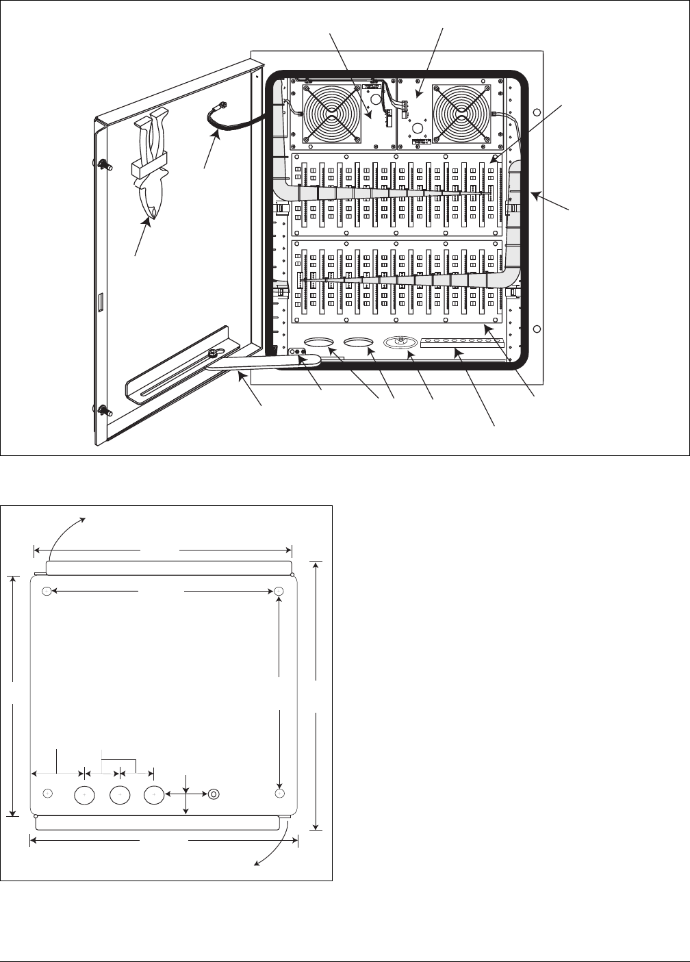
Figure 2. Cabinet Assembly, Rear View
Fan Operation and Indication
Two thermostatically controlled line powered cooling
fans limit heat buildup. The primary fan energizes at
about 110° F. The secondary fan energizes at about
150° F.
Primary and secondary fan board operation is
monitored by the FPU. The following conditions
cause an alarm at the FPU:
• Any fan or fan board not receiving power.
• Secondary fan turning On.
• Open cabinet door.
The single FPU at the CO has a separate power supply
for each fan board. The FPU fits into one slot of the
E220 HTU-C shelf (for HDSL applications).
The FPU is purchased separately. Information on fan
board operation and testing is in Section 3. For
additional details on the FPU refer to I&M Practice:
61150091L1-5. The FPU Practice should be on-hand
at the CO for reference during cabinet testing.
Figure 3. Top View Cutaway With Installation
Measurements
20 7/16"
13 3/4"
23 5/8"
20"
17"
23"
C/C
C/C
5 3/4"
View is looking down with top cut away.
Mounting bolt hole center lines are 1 5/8" in from each edge.
Ground stud is 1 5/8" from rear edge.
Measurements shown are center to center (C/C).
Door width includes locking flange.
Cable penetrations are 1 7/8" in diameter.
Cabinet is 27" high not including cable stubs.
Pad mount brackets are 18" high.
Dimensions are tape rule derived and measured from
outside the cabinet.
Rear door
Front door
OPEN
OPEN
overall
overall
A
B
spare
2 1/2" C/L
3 1/4"
cable dimensions +/- 1/8"
Ground
Lug
Secondary
Fan Board
to Cable A
Pimary
Fan Board
to Cable A
Door
Ground
Braid
Gas Tube
Extractor
Pliers
Rear Door
Retainer
Surge Arrestor Board
for bottom Shelf
Door Gasket
Surge Arrestor
Board for top Shelf
Rear Door
Switch
Ground
Buss
A, B, and Spare
Cable Penetrations
Connecting lug on
cabinet bottom
()


