2
Bosch Security Systems | 04-2003 | 3922 988 43318 en
Digital Congress Network | Installation and Operating Manual | Chapter 4 - Central Control Equipment
en | 4-15
LBB 3508/00 & LBB 3508/00D Audio Media Interface and Power Supply Unit
4.11 LBB 3508/00 & LBB 3508/00D
Audio Media Interface and Power Supply Unit
The Audio Media Interface Unit is remotely controlled by the CCU and enables external analogue
equipment to be connected to DCN’s digital network - such as broadcast, recording, and sound
distribution equipment. The unit is equipped with four Digital to Analogue convertors with channel
select switches for the selection of the floor or interpretation channels. The units built-in power supply
for up to an additional 90* PCF points. Its built-in trunk-line splitter enables the unit to be connected
to the trunk-line using the loop-through cabling method.
*The figure stated represents the number of units rated with a Power Consumption Factor (PCF) of
1. For further information regarding the Power Consumption Factor refer to Chapter 10.1.1 “System
design fundamentals”.
The unit connects to the main trunk-line cabling using the loop-through method of cabling and is
switched on automatically when the main Central Control Unit is switched on. The unit can be free-
standing on a table top or with the use of brackets supplied with the unit (Chapter 4.12) can be
mounted in to a 19” rack. Mounting the unit is similar to CCU mounting.
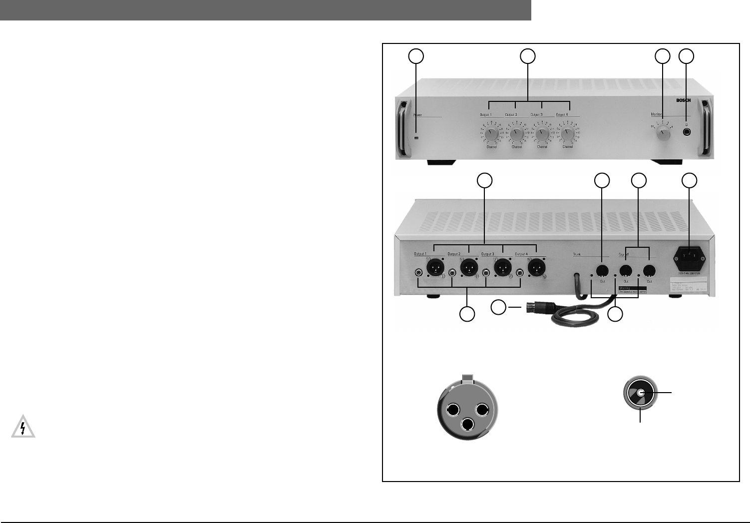
Controls and Indicators (see FIG 4-11):
1. Power On indicator (green LED).
2. 4 x 15-position rotary channel selector controls for Outputs 1, 2, 3 and 4.
3. 5-position output selector to select audio output for monitoring (Output 1 - 4 and off).
4. 6.3 mm stereo jack Headphone connector for audio monitoring.
5. 4 x 3-pin XLR male audio output sockets (balanced).
6. 1 x Trunk-line outlet connector for loop-through connection** (without regeneration) of the
trunk-line plus indicator (red LED) to indicate trunk-line overload. The outlet is protected against
short circuit of the d.c. supply lines.
7. 2 x Tap-off outlet trunk-line cable connectors** (with regeneration)***. Each outlet includes an
indicator (red LED) to indicate trunk-line overload. Each outlet is protected against short-circuit
of the d.c. supply lines.
8. Euro mains socket (a.c. mains voltage selectable inside the unit) with built-in fuse. Mains cable 1.7
m (5.5 ft.) (D-version 2.5 m (8.2 ft.) long included.
9. 3 indicators to indicate trunk-line overload (red LEDs).
10. 2 m (6.5 ft.) long cable terminated with a moulded 6-pole circular connector for connection to
the DCN Network Cable
11. 4 x audio output cinch-type sockets (Asymmetrical)
Mains connection
• For mains voltage selection, fuse rating and mains cable and plug and socket connections
refer to the Central Control Unit LBB 3500/xx. (Chapter 4.4.1). A mains tally, showing
the connection details is visible on one side of the unit once the top cover is removed.
The fuse ratings are the same as used for the CCU LBB 3500/05.
• The unit must be powered via an earthed mains outlet.
** For connection of contribution, distribution, and interpretation units, plus ext. power supplies.
*** For more information on regeneration see Chapter 10.3.
FIG 4-11 LBB 3508/00 Audio Media Interface Unit (Front and rear view)
XLR Connector
(Male)
Earth (1)
(2) Signal -
(3)
Signal +
Cinch Connector
(Male)
Signal +
Screen
1 2 3 4
5 6 7 8
11
10
9


