9. Hold the spring bar (3) perpendicular to the shank (1). Insert the upper trunnion pin into the upper
pocket of the head assembly [See figure 6]. Rotate the spring bar so the lower trunnion pin passes through
the entrance slot in the lower pocket of the head assembly.
Figure 5 Figure 6 Figure 7
10. Position lift units on trailer “A” frame. If trailer tongue consists of a single tube or other narrow member,
a pole tongue adapter (Draw-Tite P/N 3280) must be used. Hold spring bar chain vertical. Center lift units
with chain [See figure 7].
11. Turn 1/2-13 x 3-1/2 bolt until it contacts the frame. Then tighten ½ - turn with wrench. DO NOT
OVER TIGHTEN. NOTE: Optional mounting holes are provided for trailers that do not permit use of ½ - 13
bolt [See figure 8]. CONSULT TRAILER FRAME MANUFACTURER FOR APPROVAL PRIOR TO
DRILLING HOLES. 3/8” hardware is recommended whether it is self-tapping or nut and bolt.
OPTIONAL
MOUNTING
HOLES
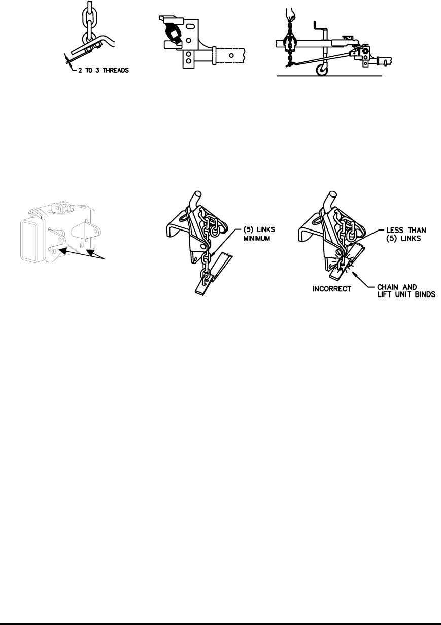
Figure 8 Figure 9 Figure 10
SPRING BAR CHAIN CONNECTION
1. With lift unit in raised position, pull straight up firmly on spring bar chain. Note which link is closest to
chain hook [See figure 7]. Countdown (2) links and that link will used for hook up.
NOTE:
BEFORE OPERATING LIFT UNIT, RAISE BUMPER OF TOW VEHICLE WITH THE TRAILER
TONGUE JACK APPROXIMATELY ONE INCH. THIS WILL REDUCE SPRING BAR TENSION AND
MAKE LIFT UNIT OPERATION EASIER.
2. Lower lift unit. Attach upper end of chosen chain link to lift unit hook, while allowing remaining free links
to fall down to the outside of the trailer frame (See figure 9).
3. There must be at least 5 links between the lift unit and the spring bar. This is necessary for proper
operation of the spring bars during turns (See figure 9). If there will be less than 5 links between the lift
unit and spring bar, the angle of the head assembly (2) must be increased. The trailer must be uncoupled
and the upper bolt removed from the head assembly. The head assembly is then pivoted down and an
additional washer is added underneath the pin [See figure 4]. Reassemble.
CAUTION: FAILURE TO CONNECT THE SPRING BAR CHAIN CORRECTLY AND PROVIDE AT
LEAST 5 LINKS BETWEEN LIFT UNIT AND SPRING BAR CAN RESULT IN DAMAGE
TO THE LIFT UNIT. FIGURE 10 SHOWS INCORRECT SPRING BAR CHAIN HOOK UP.
4. Use handle to raise lift unit. WARNING: Keep clear of all moving parts.
5. Insert spring clip on lift unit.
6. Repeat for opposite spring bar, using same number of links between hook and spring bar.
7. Retract trailer tongue jack so hitch is now carrying the full trailer weight.
VEHICLES WITH SELF ADJUSTING AND/OR AUTOMATIC LEVEL CONTROL SUSPENSIONS
Some of the newer vehicles may be equipped with some form of automatic leveling system and require
special adjustment of the weight distributing system. Please check vehicle owners manual for
recommended usage of weight distributing hitches on these vehicles.
7900 – 01APR05C PCN7753 2005 TOWING PRODUCTS, INC Litho in USA
3


