2-26
Installing the Switch
Sample Network Topologies
Installing the Switch
Because the Switch has the “IEEE Auto MDI/MDI-X” features, the connections
between the switch and the hubs, and between the switch and end nodes or
servers can be through category 5 straight-through or crossover twisted-pair
cable. Category 3 or 4 cable can also be used if the connection is 10 Mbps only.
In all cases, the device ports must be configured to auto negotiate the link
characteristics for this feature to work.
The switch, in turn, can be connected to a network backbone through fiber-
optic cabling connected to a Gigabit-SX, -LX, or -LH mini-GBIC installed in the
switch. Now, all the devices on these network segments can access other
network resources that are connected elsewhere on the network backbone.
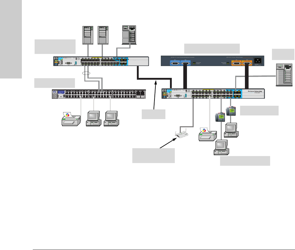
Figure 2-19. As a Segment Switch Implementing PoE.
As shown in figure 2-19, the IP telephones have been inserted in between the
3500yl-PWR switch and the PCs, and a WAP has been connected to the 3500yl-
PWR switch. Both the telephones and WAP will receive PoE power from the
3500yl-PWR switch. Only devices directly connected to the PWR switches can
receive PoE power. Devices connected to a non-PWR switch cannot receive
PoE power.
Server
PCs and peripherals
ProCurve Switch
3500yl-24G
IP Telephones
ProCurve 620 RPS/EPS
10-GbE
Wireless Access
Point
Non-PoE Switch


