111132_0409 4-5
1. Locate the height of cut bar and loosen the locknut.
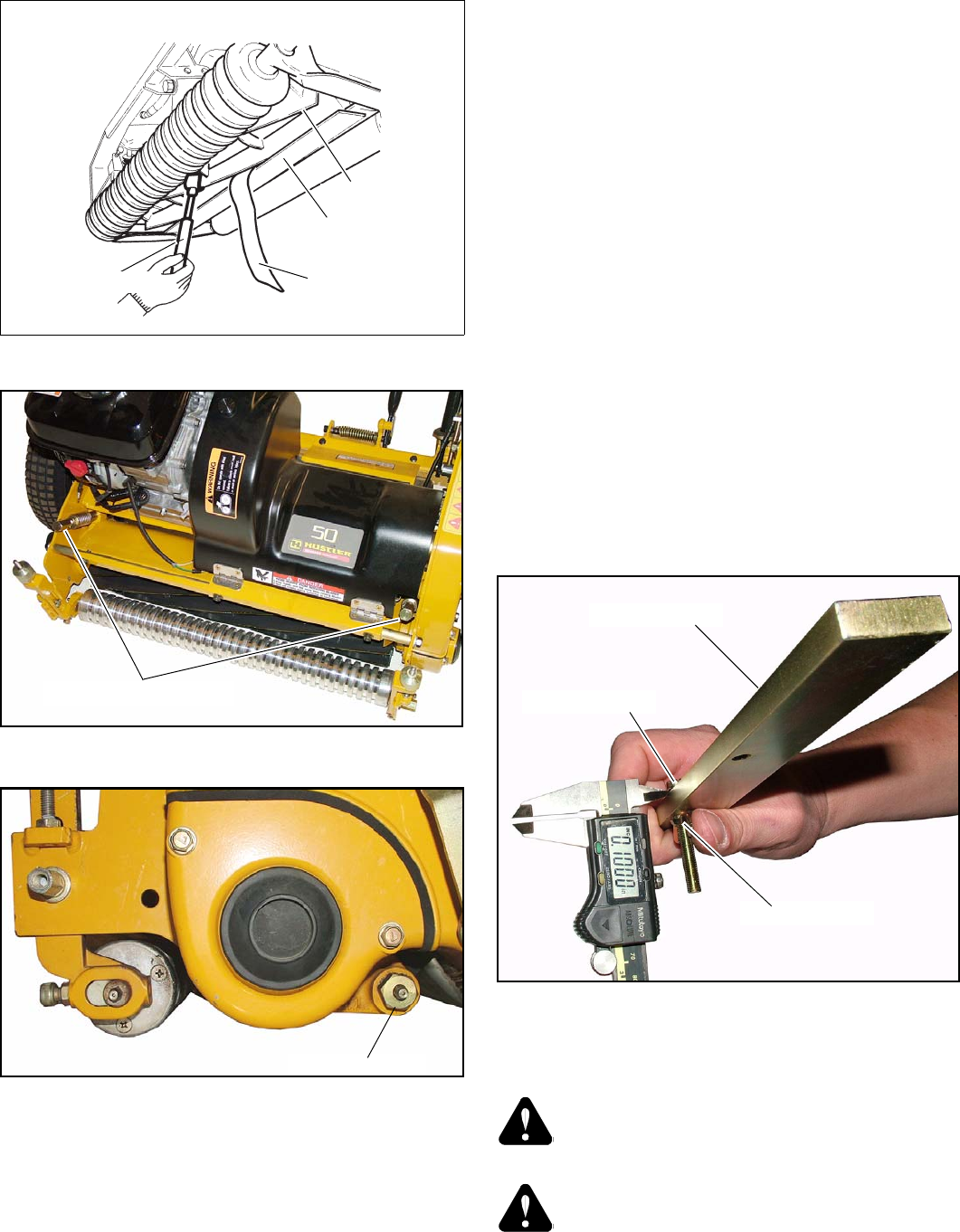
Adjust the screw to the desired height of cut by
measuring the distance between the top of the HOC bar
and the bottom of the screw head as shown. (Fig. 4-11 &
Fig. 4-12) Once adjusted, tighten the lock nut.
2. Park the machine on a level surface. Tilt it back to
provide good access to the bedknife, front roller, and
drive roller. Secure the machine in position so it will not
move.
3. Loosen the height adjustment lock nut on both sides.
(Fig. 4-13)
4. Loosen the jam nut on the threaded adjusting rod on both
sides. (Fig. 4-13)
5. Raise the front roller by turning the roller height
adjusting knobs on both sides in the clockwise direction.
6. On the right hand side, install the HOC bar with the rear
of bar pressed up against the drive roller in the rear, then
hook the bolt head over the bedknife cutting edge. The
HOC bar should be perpendicular to the bedknife.
Fig. 4-14 & Fig. 4-15
7. Lower the front roller down, evenly turning both
adjusting knobs, to the HOC bar so it comes into contact
with the HOC bar, but still allows the HOC bar to be
removed.
8. Install the HOC bar on the LH side and adjust the front
roller as necessary to come in contact with the HOC bar.
Re-check the center, RH and LH sides again to make sure
the front roller is properly adjusted and the height is set
correctly across the full width of the unit.
9. Tighten the jam nuts on the threaded adjusting rod on
both sides.
10. Tighten the height adjustment locknuts on both sides..
Backlapping operation
WARNING: Always stop the engine and disengage
the traction drive and cutting reel drive before back-
lapping.
WARNING: When using the backlapping machine
and turning the reel blade do not allow your hand,
foot, or any part of your clothing, near the cutting
range.
Fig. 4-8
Fig. 4-9
Fig. 4-10
Newspaper
Bedknife
Reel blade
Bedknife adjusting screws
Fig. 4-11
Height of cut bar
Screw head
Lock nut
Blade alignment tool


