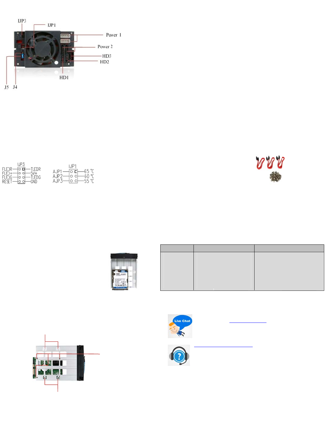
Har
POWE
POWE
(may
HD1—
lJP1: T
lJP3: E
J4: FA
(Every
stop. I
J5: HD
IJP1
FLEDR
FLED+
FLEDG
TLEDR
TLEDG
GND:
2.5”
wareInform
R1: 4pin Power c
R2: 15pin Serial
se any two type
HD3: 7pin Serial
mperature settin
tension function
RPM Switch: HI
time when you t
will run again w
D LED Switch (def
IJP3Jump
:Fan failure detec
Fan failure detec
:Fan failure dete
:Temperature de
:Temperature de
rounded
or3.5”Hard
. Insert 2.5” o
HDD Tray fro
. Use the prov
into highligh
cage trays.
. Make sure S
the Bottom
. After the scr
Tray back to
. Next, follow
page for the
3.5” HD Scre
ation:Rear
nnector.
TA Power connec
f power connect
TA Signal connec
g jumper (default
jumpers
H & AUTO Optio
rn on the powe
,
en temperature r
ult: Enable)
rpinsetting
tion (red).
ion (+)
tion (green)
ection (red) 5V+:
ection (green)
DriveDiskt
3.5” Hard Drive i
the cage.
ded screws and f
ed 2.5” or 3.5” h
cure with screw
f 2.5” or 3.5” Har
w installation, sli
he HDD Canister
he Quick Installat
est of the Setup.
3.5” HD Screw H
Holes
iew
or.
r)
or
: 55º C)
al.
he fan runs for 1
aches 40º C.)
:
V Power
thetraysIn
to the
sten HD
les to the
oles from
Drive’s.
e the HDD
ase.
ion in next
les
Tray: Bottom
2.5”
Hol
seconds and the
tallation:
PU-230SATA
BPU-230SATA
ew
HD Screw
s
n
QuickI
1
2
3
4
5
6
7
Note:
Forsteps
sureyou
For optio
instructio
Access
3S
Scre
Option
iStarU
FCC and CE Rad
FCC
This equipment
Commission (FC
CE
This equipment
states relating to
FCC and CE Co
These limits are
and can radiate
communication.
equipment off a
receiving antenn
that to which the
CAUTION!
The Federal Co
for the complian
HDTr
Bla
Re
Blu
Silv
Plas
nstallationP
. Open up the
cage.
. Secure all scr
. Place the har
. Push the han
. Connect all n
unit.
(Make sure t
well).
. Turn on the P
finish loading
. Turn on all ne
installed.
6‐iftheoperatin
oturnonthePo
al RAID Configur
s from your SAS
ries:
TAcables
ws
alAccessori
Acare:
Wewill
younee
abovet
Ourtech
http://ist
supportti
end.Ory
iation Norm
as been tested and found to
C) rules.
as been tested and found to
electromagnetic compatibilit
pliance Statement
esigned to provide reasonab
adio frequency energy, and if
However, there is no guarante
d on. The user is encouraged
a, Increase the separation bet
receiver is connected to.
munications Commission wa
e could void the user’s autho
ays Model
k
r
ic
BPU‐HS
BPU‐HS
BPU‐HS
BPU‐HS
BPU‐HS
rocedure:
andle bar from t
ws to the HD att
drive tray(s) wit
ling bar into clos
cessary data and
at the date cable
ower of your com
up.
cessary HD1~HD
systeminstalled
erfromthecag
tion & Setup pro
SATA Controller C
s:
elpyounavigate
.Gotowww.ist
eSearchBar
niciansarestand
rusa.com/suppo
ckettohelptrack
ucancontactus
omply with limits for Class B
omply with the limits of the E
(89/336/EEC) according to E
le protection against frequenc
not installed or used in accor
e that interference will not oc
to try and correct the interfer
een the equipment and the r
ns the user that changes or
rity to operate the equipment
.
umber
RAY‐BLACK
RAY‐RED
RAY‐BLUE
RAY‐SILVER
RAY
e tray; take out t
ched with HD tra
HD installed, ba
d position.
power cable ont
connected to th
puter and wait u
Power Button(s)
withaHDinside
switchesD2/D3
edure, please foll
rd or Motherboa
ourwebsitetofi
rusa.com,andcli
ngbytotakeyo
t/,andyouwill
yourrequestsfr
888‐989‐1189
igital device pursuant to Part
ropean Council Directive on
55022 Class B.
interference in residential in
ance with the instructions ma
ur in television reception, whi
nce by one or more of the foll
ceiver, connect the equipmen
odifications to the unit not ex
U
846
846
846
846
846
e HD trays from
.
k into the cage u
the rear end of c
motherboard si
til Operating Syst
for each Hard Dri
ofHDcage,plea
orD4.
ow the user man
rd.
dtheinformatio
konlivechatbu
rquestions.Visit
eceiveatechnic
mthebeginning
15 of Federal Communication
he approximation of the law o
tallation. This equipment gen
y cause harmful interference t
h can be determined by turni
wing measures: Reorient or
t into an outlet on a circuit dif
ressly approved by the party
PCCode:
13000635
13000659
13000642
13000673
13000628
BPU-230SAT
BPU-230SA
he HD
it.
ge
e as
m
e
emake
al
nthat
ble
l
othe
the member
rates uses
radio
g the
elocate the
rent from
esponsible
A


