u
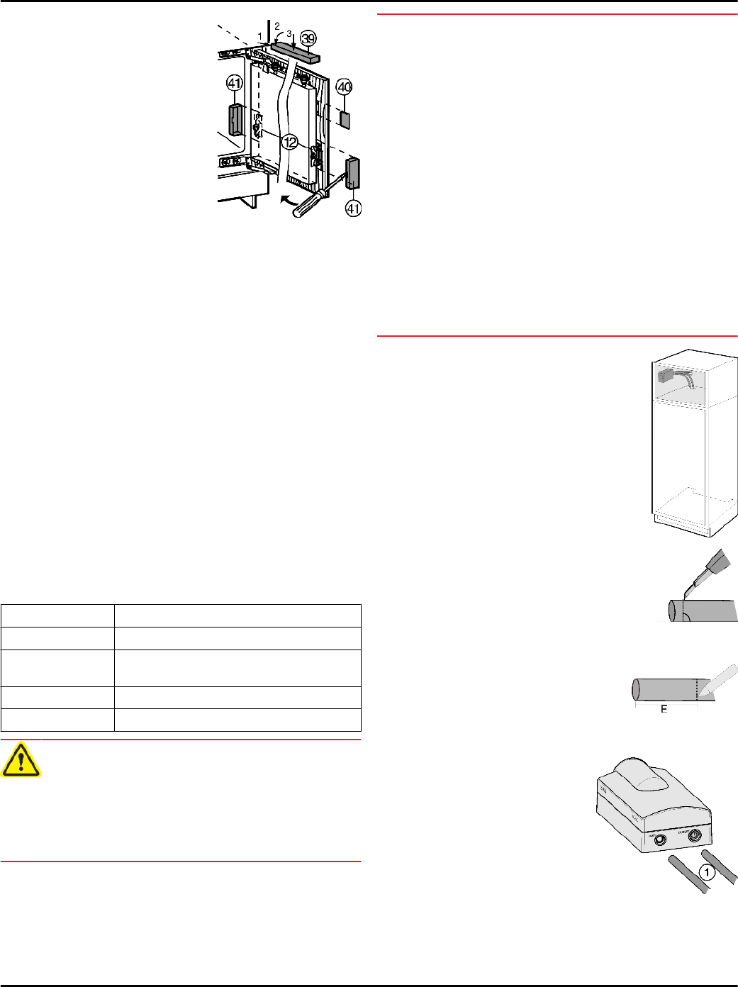
Position the upper cover
Fig. 31 (39)
and snap into
place.
u
Place the lateral cover
Fig. 31 (40)
in position, slide
to the limit and then press
until it snaps audibly into
place.
u
Attach covers
Fig. 31 (41)
to
the side and then draw
them forward with a
screwdriver, so that they
snap properly into place.
Fig. 31
With a 24 '' (609.6 mm) wide recess:
u
Position the covers
Fig. 11 (6,7,42)
and snap them into
place.
With a 23-5/8 '' (600 mm) wide recess:
u
Position the covers
Fig. 11 (4,6,7)
and snap them into
place.
Check the following points to make sure the appliance is
installed correctly. Otherwise, icing up, the formation of
condensate, and malfunctions can occur.
w
The door must close properly.
w
The unit door must not touch the body of the unit.
w
The seal on the upper corner on the handle side must be
fitted securely. To verify this, darken the room, place a
flashlight in top part of the appliance, and close the door.
If you see light shining out, check the assembly.
7 Installing the water filter*
The water filter guarantees optimal water quality and should
be installed the first time you use the appliance.
Alternatively, the appliance can also be operated without
the water filter.
Flow rate 0.5 gpm (1.89 lpm)
Water connection Public or private source
Water pressure 40 psi - 90 psi ( 2.8 bar - 6.2 bar/ 0.28 MPa
- 0.62 MPa )
Water temperature 33 °F - 100 °F ( 0.6 °C - 37 °C )
Capacity 500 gal. (1893 l)
WARNING
Consuming contaminants can be harmful to your health!
u
If there is a chance the water may contain harmful
bacteria or if the water quality is unknown, do not use this
system without appropriate disinfection measures
upstream or downstream of the system.
NOTICE
Leakage water may damage the system!
u
Do not install this system on hot water lines. The
maximum operating temperature of the water in this
system is 100 °F (37.7 °C).
u
This system MUST be installed and used in compliance
with federal and local installation regulations.
u
Do not install under water hammer conditions. A water
hammer arrestor must be used to prevent water
hammering. If you are unsure how to check these
conditions, consult a professional installer.
u
Do not install with a water pressure greater than 90 psi
(6.2 bar). If your water pressure exceeds 80 psi, install a
pressure limiting valve. If you are unsure how to check
the water pressure, consult a professional installer.
u
Protect against frost; if temperatures below 33 °F
(0.6 °C) are expected, remove the filter.
u
When used as indicated, the disposable filter cartridges
must be replaced every 6 months or whenever you notice
a considerable decrease in the flow rate.
Make sure that the following conditions are
fulfilled:
q
The hoses have been positioned such
that they can now be connected to the
filter.
q
The installation position has been
selected according to the instructions
(see 4.3) .
q
The connectors have been removed from
the hose ends.
u
Hoses have been shortened, if necessary
(cut at 90° angle to the direction of the
hose).
When doing so, make sure the hoses do not become kinked
and the cross-section of the hose remains round.
u
On the thin hose, measure the
insertion depth (E) of 21/32 '' (17 mm)
and mark it.
u
On the thick hose, measure the
insertion depth (E) of 25/32 '' (20 mm)
and mark it.
u
Insert the hoses
Fig. 32 (1)
all the way into
the water filter module
(i.e., up the the mark you
made), past the point of
resistance.
Fig. 32
Installing the water filter
13


