7
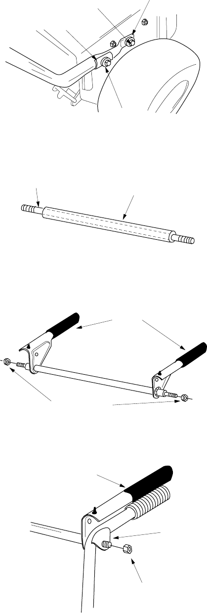
Figure 4
Figure 5
Figure 6
Figure 7
ATTACHING THE HANDLES
(Hardware A)
1. Place right handle in position against the snow
thrower so the flat side of the handle is against
the frame. Secure bottom hole in handle to
snow thrower using hex bolt (B) and lock
washer (C). There are weld nuts welded to the
inside of the frame for these bolts. See Figure
4. Do not tighten at this time.
2. Attach the left handle in the same manner. Do
not tighten at this time.
3. Place saddle (I) over upper holes on handles
(curve matching curve on handle). Secure to
the frame with lock washers (C) and hex bolts
(A). See Figure 4. Do not tighten at this time.
ATTACHING THE CLUTCH GRIPS
(Hardware B)
1. Slide the pivot rod into the cover tube as shown
in Figure 5. The pivot rod and cover tube may
already be assembled.
2. Place the clutch grips in position on the rod so
the flat side of the clutch grips are against the
pivot rod cover. Thread hex nuts (D) onto each
end of the rod. Tighten nuts allowing the clutch
grips to move freely on pivot rod. See Figure 6.
3. Insert clutch grip and rod assembly into handle
tabs. Clutch grips must sit on top of the
handles. Thread hex nuts (D) on each end to
hold into position. Do not tighten. See Figure 7.
Lock Washer
(C)
Hex Bolt
(B)
Saddle
(I)
Hex Bolt
(A)
Lock Washer
(C)
Pivot Rod
Cover Tube
Clutch
Grips
Hex Nuts (D)
Clutch Grip and
Rod Assembly
Handle
Tab
Hex Nut (D)


