1
DCA25USIXF/DCA25USI2XF — OPERATION AND PARTS MANUAL — REV. #2 (07/26/11) — PAGE 21
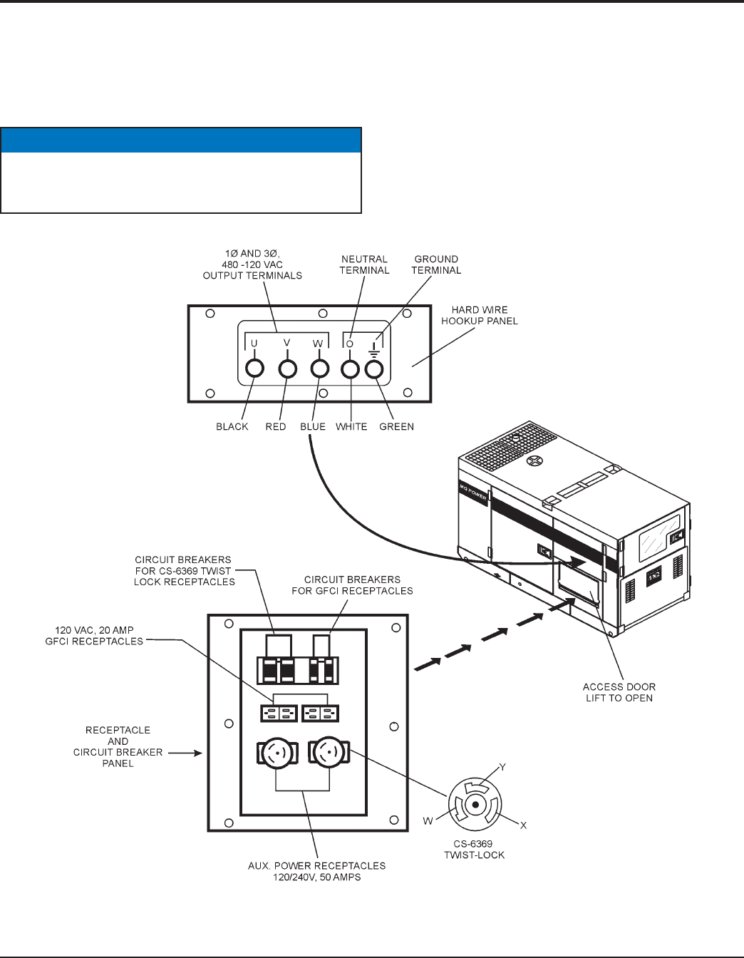
Output Terminal Familiarization
The “
Output Terminal Panel
” (Figure 6) is provided with the
following:
■■
■■
■
Two (2) 120/240V output receptacles @ 50 amp
■■
■■
■
Two (2) Circuit Breakers @ 50 amps
■■
■■
■
Two (2) 120V GFCI receptacles @ 20 amp
■■
■■
■
Two (2) GFCI Circuit Breakers @ 20 amps
■■
■■
■
Five (5) Output Terminal Lugs ( U, V, W, O, Ground)
Output Terminal Panel
The
Output Terminal Panel
(Figure 8) shown below is located
on the right-hand side (left from control panel) of the generator.
Lift up on the cover to gain access to receptacles and terminal
lugs.
Figure 8. Output Terminal Panel
■■
■■
■
One Main Circuit Breaker @60 amps
OUTPUT TERMINAL PANEL
Terminal legs “O” and “Ground” are considered
bonded
grounds
.
NOTICE


