LT12D50SA LIGHT TOWER • OPERATION MANUAL — REV. #0 (03/16/09) — PAGE 23
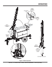
Light tower is placed on secure level ground with chock
blocks underneath each wheel to prevent the light tower
from rolling.
Outriggers have been fully extended to prevent the trailer
from tipping.
Light tower trailer support stands have been positioned
properly and the trailer is level.
Lamps have been adjusted to desired position.
Light tower trailer frame has been grounded correctly.
Lamps do not interfere with any overhead obstructions.
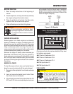
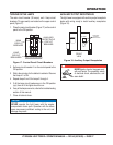
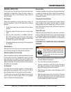
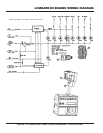
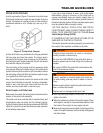
Lamp power cables have been plugged into the
appropriate receptacles (J1-J4) on the T-Bar assembly.
Follow instructions below to correctly install the power
cable plugs.
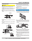
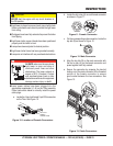
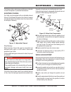
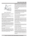
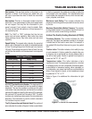
Locate the 4 key-lock female 3-pin DIN connectors a.
on the T-bar. See Figure 10.
Location of Female ConnectorsFigure 10.
CAUTION
NEVER start the engine with any circuit breakers in
the ON position.
DANGER
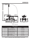
ALWAYS make sure the area above
light tower is open and clear of
overhead power lines and other
obstructions. The tower extends in
excess of 30 ft. (9 meters). Contact
with overhead power lines or other
obstructions could result in equipment
damage, serious injury or death!
KEY-LOCK
FEMALE
CONNECTORS
INSPECTION
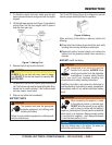
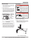
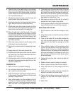
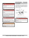
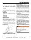
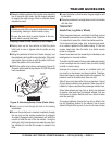
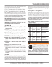
Locate the slot or key (A) on each female connector b.
as shown in Figure 11.
Female ConnectorFigure 11.
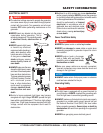
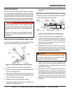
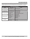
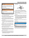
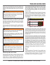
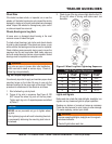
On the corresponding male connector, locate the c.
key tab (B) as shown in Figure 12.
Male ConnectorFigure 12.
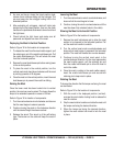
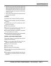
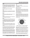
Align the key tab (B) on the male connector with d.
the slot or key (A) on the female connector and
press together until fully seated.
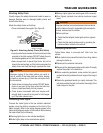
Secure the connector by screwing the knurled e.
locking nut of the male connector to the threaded
portion of the female connector to ensure
good contact between the two connectors. See
Figure 13.
Cable ConnectorsFigure 13.
B
J1
J2
J3
J4
LOCKING
NUT