SP1E16A PAVEMENT SAW • OPERATION MANUAL — REV. #0 (04/14/10) — PAGE 15
CONTROLS AND COMPONENTS
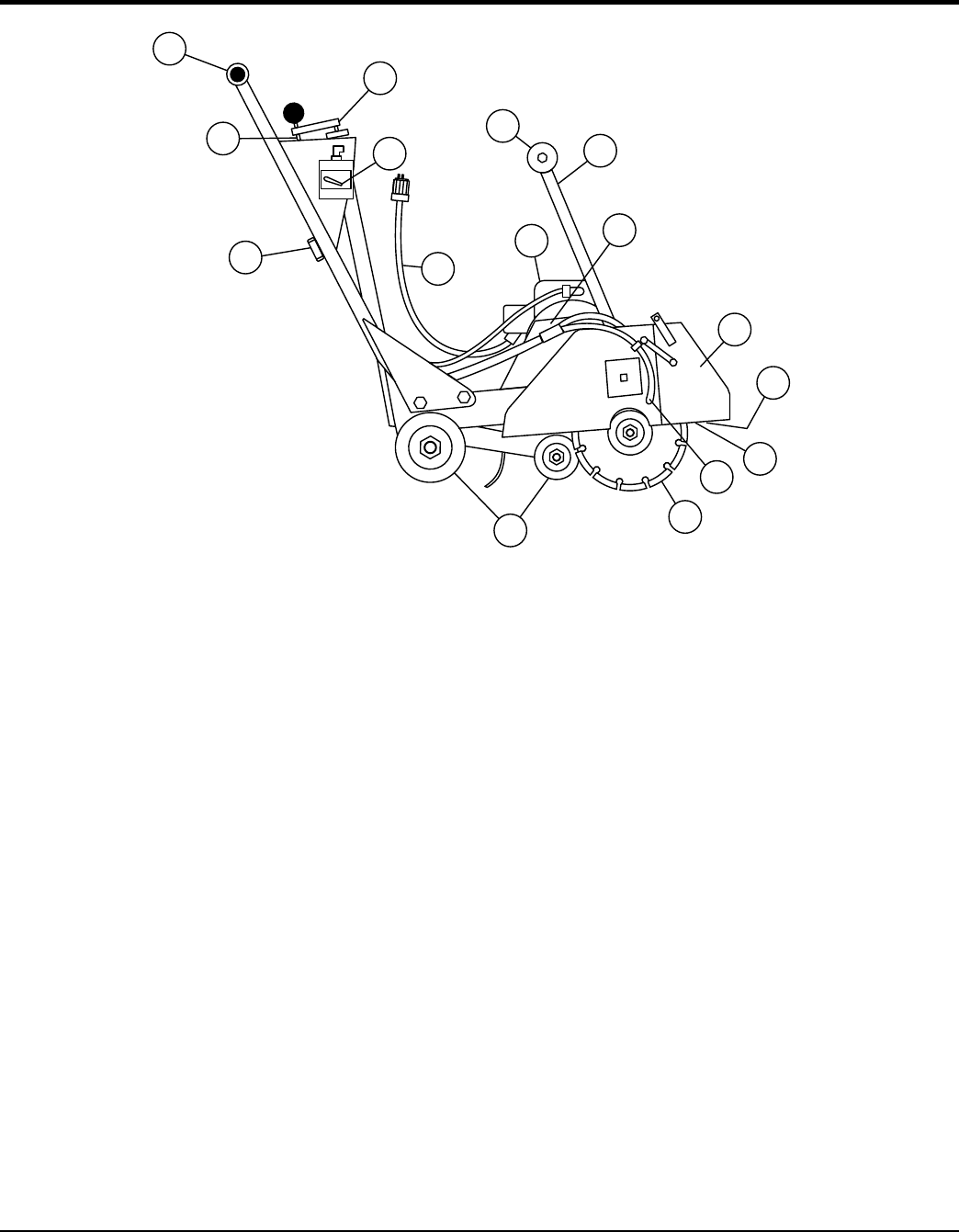
Figure 2 shows the location of the basic controls and
components for the SP1E16A. Listed below is a brief
explanation of each control or component.
1. Hand Grips/Handlebar — When operating the saw,
place both hands on each grip to maneuver the saw.
Replace hand grips when they become worn or
damaged.
2. Handle Lock — Lock blade depth to desired
position.
3. Garden Hose Connecter — Connect to water source
to provide blade cooling while cutting concrete or
asphalt.
4. Wheels/Carriage Assembly — Heavy-duty
polyurethane wheels with permanently sealed ball
bearings.
5. Cutting Blade — Use appropriate type blades for
cutting concrete or asphalt. Requires 1" arbor.
6. Blade Guard — Covers saw blade and flips up to allow
blade to be changed.
7. Belt Tension Adjuster — Adjusts belt tension.
8. Front Pointer — Front pointer wheel assists in straight
tracking.
9. Front Pointer Arm — Stows up for storage and pivots
down for use.
10. Cutting Depth Adjuster — turn operating crank
clockwise or coun ter-clockwise to adjust the cutting
depth up or down.
11. Blade Coolant System — Provides cooling water to
blade during cutting operations.
12. V-Belt Cover — Remove this cover to gain access
to the V-belt. NEVER operate the saw with this cover
removed.
13. Arbor Shaft Grease Zerks — Conveniently located
for lubrication.
14. On/Off Switch — Turn to the "ON" position to allow
motor to be started and turn to the "OFF" position to
shut the motor off.
15. Electric Motor — 230 VAC, 60 Hz, single phase @
19.5 Amps
16. Power Cable — Connect to a 230 VAC, power source
@ 19.5 Amps.
Figure 2. SP1E16A Controls and Components
1
2
3
4
5
8
9
10
7
13
14
15
16
12
6
11


