ANALYTICAL METHODS FOR TEXTILE COMPOSITES
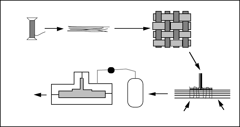
Yarn
(Thousands of Fibers)
Dry Preform
Thickness of
order 1 - 10 mm
Figure 2-1. Steps in the production of a textile composite structure.
The fabrication method of Figure 2-1 also illustrates fairly high utilization of the
axial stiffness and strength of the fibers. The fibers in the skin are arranged approximately
in-plane and straight and with reasonably high volume fraction. High in-plane composite
stiffness and strength can therefore be expected. Certain other traditional textiles do not
achieve this. For example, many knitted fabrics loop yarns in highly curved paths, rather
than aligning them; and, because of the openness of the fabric, can achieve only moderate
fiber volume fractions. Composite stiffness and strength are consequently inadequate for
airframes. For similar reasons, fiber mats and discontinuous reinforcements are usually
unattractive to airframe designers. These materials will be excluded from further
consideration in the handbook.
Figure 2-1 also exemplifies reinforcement that is heterogeneous on the scale of the
structure. The length of the stitches varies with the thickness of the flange of the rib and
their spacing is not far below the thickness of either the rib itself or the flanges. Just as the
material and the structure are fabricated simultaneously, so in this case they must be
analyzed simultaneously. Dealing adequately with the fiber architecture in determining
stress distributions requires analyzing the external geometry of the part itself. However,
computer programs to perform such a task are still being developed. Therefore, this
handbook in its first edition focuses on solutions for skins, sheets, or slabs without
complicating external shapes, for which developed and tested programs are already
available.


