INPUT
MENU
VOL
ENTER /
+
/
-
/
14
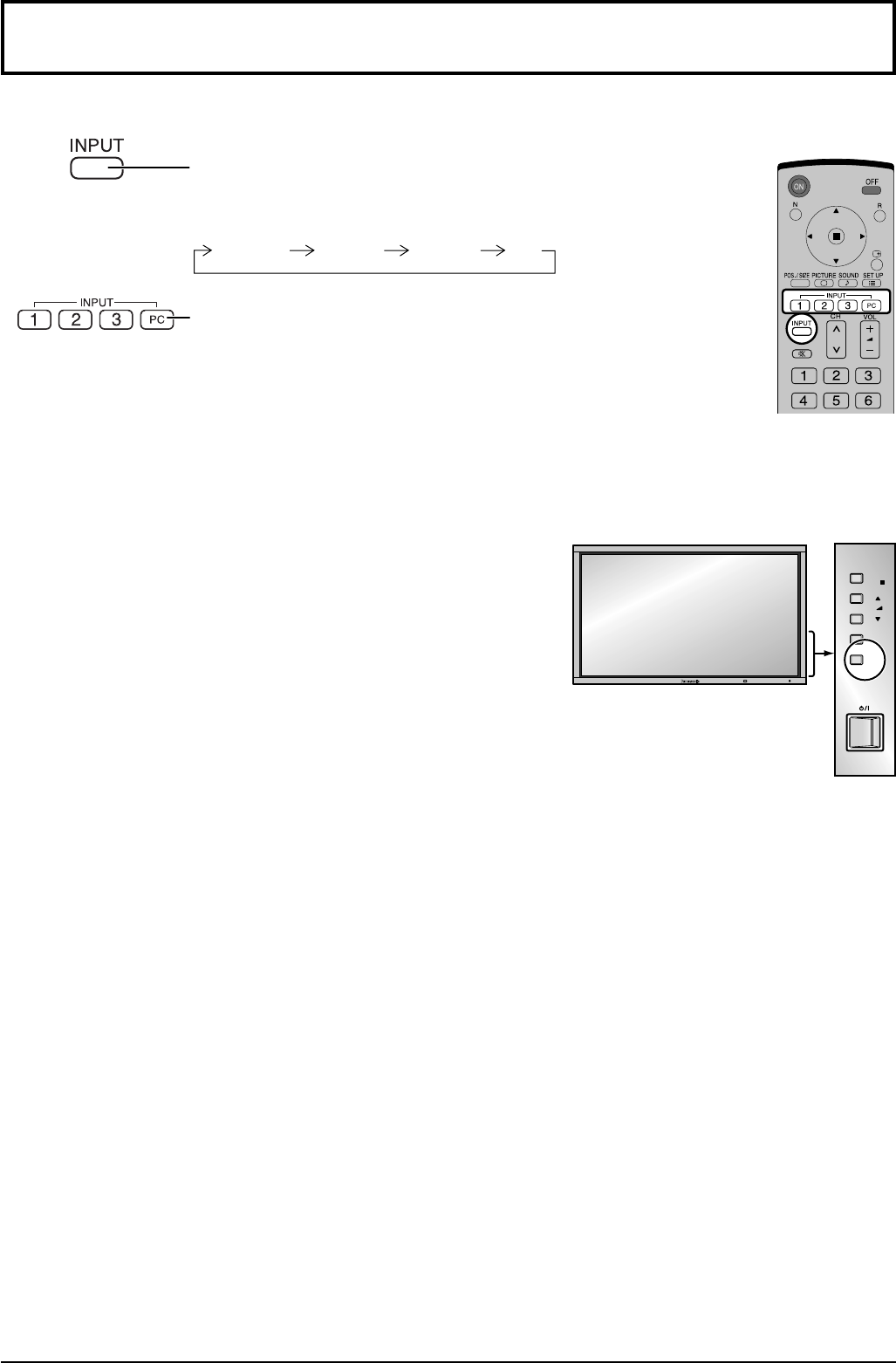
Selecting the input signal
Notes:
• Selecting is also possible by pressing the INPUT button on the unit.
• Input terminal will not be selected if the terminal board is not installed
into the SLOT.
• Select to match the signals from the source connected to the
component/RGB input terminals. (see page 48)
• In 2 screen display, the same input mode cannot be selected for the
main picture and sub picture.
• Image retention (image lag) may occur on the plasma display panel
when a still picture is kept on the panel for an extended period. The
function that darkens the screen slightly is activated to prevent image
retention (see page 61), but this function is not the perfect solution to
image retention.
Select the input signals to be connected by installing the optional Terminal Boards.
Press to select the input signal to be played back from the
equipment which has been connected to the Plasma Display.
Input signals will change as follows:
INPUT2 PC
INPUT3INPUT1
Press the INPUT “1”, “2”, “3” or “PC” input mode selection button
to select the input mode.
This button is used to switch directly to INPUT mode.
These buttons can only display the slot which is installed. If
you press the button whose slot is not installed, it automatically
displays the current input signal.
When a dual input terminal board is attached, A or B is displayed
depending on the selected input signal. (Ex. INPUT1A,
INPUT1B)


