A
E
C
B
D
F
Page 5
A
6"
5
B
D
C
1
⁄
4”
1
1
⁄
4”
A
1⁄4"
1
1
⁄4"
3
Installation Continued
2. Selecting the Faucet Location
The drinking water faucet should be positioned with function, convenience and appearance in
mind. An adequate flat area is required to allow faucet base to rest securely. The faucet fits
through a 1
1
⁄4-inch hole. Most sinks have pre-drilled 1
1
⁄2-inch or 1
3
⁄8-inch diameter holes
designed for spray hoses. The drinking water faucet may be installed using one of these holes,
despite their larger size. If these pre-drilled holes cannot be used or are in an inconvenient
location, it will be necessary to drill a 1
1
⁄4-inch hole in the sink or through countertop next to
the sink for the faucet.
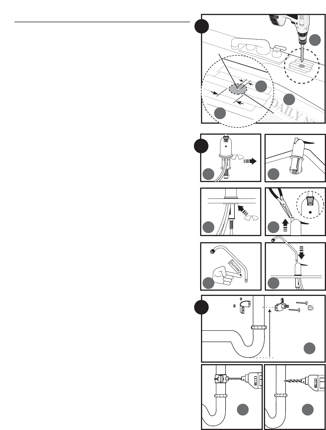
3. Drilling the Faucet Hole
CAUTION: This procedure may generate dusts which can cause severe irritation if inhaled
or come in contact with the eyes. The use of safety glasses and respirator for
this procedure is recomended.
CAUTION: DO NOT ATTEMPT TO DRILL THROUGH AN ALL-PORCELAIN OR PORCELAIN-
COATED SINK. For applications on these types of sinks we recommend using the
sprayer hole or mounting the faucet through the countertop.
CAUTION: When drilling through a countertop make sure the area below the drilled area is
free of wiring and piping. Make certain that you have ample room to make the
proper connections to the bottom of the faucet.
CAUTION: Do not drill through a countertop that is more than 1-inch thick.
CAUTION: Do not attempt to drill through a tiled, marble, granite or similar countertop.
Consult a plumber or the countertop manufacturer for advice or assistance.
The following instructions apply to stainless steel sinks only.
(A) Line bottom of sink with newspaper to prevent shavings, parts or tools from falling down
drain.
(B) Place masking tape over the area to be drilled to prevent scratches if drill bit slips.
(C) Mark point with center punch. Use a 1/4-inch drill bit to drill a pilot hole through sink.
(D) Use a 1
1
⁄2-inch hole saw to enlarge hole. Smooth rough edges with a file.
4. Mounting the Faucet
(A) Loosen brass stem-nut on faucet, remove metal "C" disc.
(B) Holding the faucet, feed the three tubes through the hole in the sink. Position the faucet
handle at a desired location.
(C) Center the faucet and slip "C" disc between the white spacer and the bottom of the
counter or sink. Tighten the stem nut with a wrench until it is tight.
(D) Making sure the faucet handle is in the down position, use a needle-nose pliers to pull the
short plastic tube out of the top of the faucet base.
NOTE: If handle should come off faucet base, make sure the T-Bar is parallel to the
front of the faucet base before inserting handle. If T-Bar is not in the correct
position, the faucet will not work properly.
(E) Lubricate the o-rings on the bottom of the faucet spout with supplied silicone lubricant.
Use lubricant sparingly.
(F) Insert goose-neck spout into faucet base firmly.
5. Installing the Drain Clamp
NOTE: If you have a single-basin sink with a disposal unit, call Technical Support for
options.
NOTE: Before installing the drain clamp, check the drainpipes under the sink for
corrosion. Corroded pipes should be replaced before continuing with
installation.
(A) Attach the drain clamp to a vertical section of the drainpipe, about 6-inches above the
trap. Make sure the opening on the drain clamp is facing towards the drinking water
faucet.
(B) Using the fitting hole of the drain clamp as a guide, drill 1/4-inch hole through one side of
the drainpipe.
(C) Remove the drain clamp from the drainpipe and enlarge the hole with a 3/8-inch drill
bit.Use a file to remove rough edges from the drilled hole.
(D) Make sure the black rubber gasket is adhered to the inside of the drain clamp and place
the drain clamp assembly over the drilled hole. Look through the hole and position the
clamp so that the center of the clamp hole is slightly higher (about 1/16-inch) than the
center of the drilled hole. (See figure 5 D on page 6). Tighten the clamp securely.
(E) Screw the plastic compression nut onto the drain clamp until hand-tight. (See figure 5 E
on page 6).
C
D
Pilot Hole
Mounting Hole
B C
4