ANALOG INPUT SECTION 10
Page 10-1 RPC-320
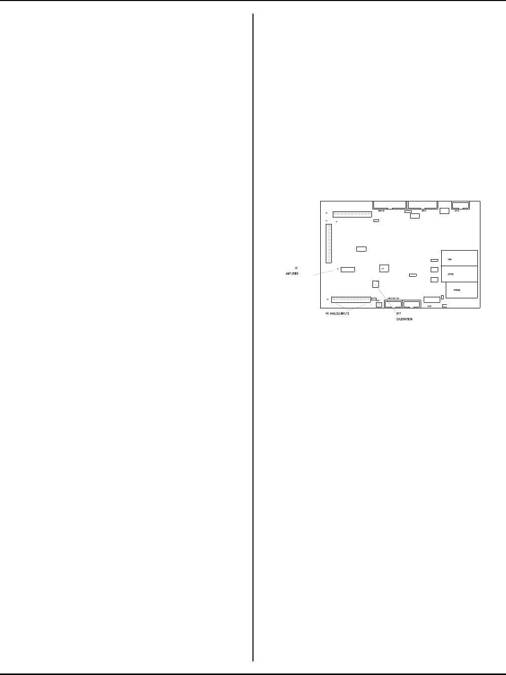
Figure 10-1 Analog I/O
DESCRIPTION
The RPC-320 has 8 single ended analog input channels.
These channels are used to measure voltages from
transducers, 4-20ma current loops, thermistors, etc.
Input voltage range is 0 to 5 volts or ±2.5V with 12 bit
(4096 count) resolution. Signals are single ended or
differential. Input impedance is 100K ohms to ground.
Reference IC U14 has a voltage output that corresponds
to the IC tem perature. T his output may be used to
measure ambient temperature.
Two amplifiers are available to signal condition inputs.
By installing appropriate r esistors and capacitors, inputs
are buffered, amplified, and filtered.
This chapter begins with basic information on connecting
and using analog inputs. Later, descriptions of how to
measure voltages other than 2.5 or 5 volts, temperature
measurement, data logging, using the amplifiers, and
calibration are presented.
CONNECTING ANALOG INPUTS
All analog inputs interface through connector P4.
Additional components, such as resistors and capacitors,
may be connected directly to the screw terminals.
For greatest accuracy, connect unused inputs to ground.
R17 is adjusted to trim accuracy to your system. See
Calibration later in this chapter for more information.
Temperatur e output or other signal input may go directly
to channel 0 via header H1. See Temperature
Measurement and Amplifiers below.
Overvoltage conditions
Inputs are protected over voltage protected. Maximum
voltage on 1 channel is 25 volts. Maximum voltage for
2 to 4 channels is 12 volts. Total input current may not
exceed 16 ma on all channels. Each channels input
current is computed by the following formula:
I
in
= (V
in
- 5)/4700
When V
in
< 5 volts, no current flows into the channel.
NOTE: An over-voltage condition on one channel
usually affects readings on other channels.
Grounding
Analog ground is somewhat isolated from digital ground.
While the ground plane is connected between the two,
analog ground is a virtual "island" connected only in one
place to digital ground. To minimize noise pickup, the
sending device should be connected to analog ground
(located at the analog input terminal strip). W hen both
analog and digital grounds come from the same device,
you will have to play around with the grounds to
determine which scheme provides the best performance
for your system.
INITIALIZATION
Each channel is initialized for 0-5V, single ended input
upon power up. Inputs can be reconfigured for eight
single-ended, four differential, or a mixture of single-
ended and differential inputs. Input voltage ranges are 0
to 5V or ±2.5V for any single-ended channel or
differential pair. Syntax is:
CONFIG AIN channel,mode, range
channel ranges from 0 to 7 for single-ended inputs.
Differential inputs use adjacent channels.
mode defines single-ended or differential. 0 =
differential, 1 = single-ended.
Differential inputs operate in a special way. The
polarity of the input signal must be connected as shown
for an even or odd channel. For example, when channel
is odd (1, 3, 5, or 7), channel 0 must be more negative
than channel 1 otherwise a 0 is returned. Should the
relative polarity change, configure the even channel for
differential input and perform an AIN on it. Use the


