ENGLISH
GB
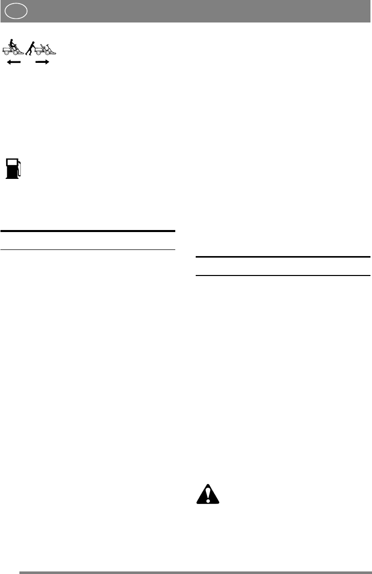
1. Lever moved back – transmis-
sion engaged for normal opera-
tion.
2. Lever moved forward – trans-
mission disengaged. The ma-
chine can be moved by hand.
The machine may not be towed over long distances
or at high speeds. The transmission could be dam-
aged.
19. FUEL GAUGE/FUEL CAP
Fuel cap with built-in fuel gauge that indi-
cates how much fuel there is in the fuel
tank (applies to Royal-Pro16-Pro20).
Comfort and President have a fuel cap without a
fuel gauge.
The fuel tank holds approx. 11.5 litres.
AREAS OF USE
The machine may only be used for the following
tasks using the genuine STIGA accessories stated.
1. Mowing
Using cutting deck 13-2939 (92M), 13-2927/
13-2935 (107M), 13-2951/13-2952 (107 M
HD), 13-2915/13-2921 (121M), 13-2936/13-
2937 (125 Combi Pro) or flail mower 13-1977.
2. Sweeping
Using brush unit 13-1933 or collector brush
unit 13-1939. Use of dust guard 13-1936 is rec-
ommended with the first option.
3. Snow clearance
Using snow blade 13-0918 or snow thrower 13-
1948. Snow chains 13-0936 (16“)/13-0937
(17“) and frame weights 13-0923 are recom-
mended.
4. Grass clipping and leaf collection
Using towed collector 13-1978 (30") or 13-
1950 (42").
5. Grass and leaf transport
Using dump cart 13-1979 (Standard), 13-1988
(Maxi) or 13-1992 (Combi).
6. Sand spreading
Using sand spreader 13-1975. Can also be used
for spreading salt. Snow chains 13-0936 (16“)
13-0937 (17“) and frame weights 13-0923 rec-
ommended.
7. Weeding on gravel paths
Using front mounted hoe 13-1944 and rear-
mounted rake 13-1969.
8. Lawn edge trimming
Using edge trimmer 13-0905.
9. Moss scarification
Using moss scarifier 13-1984.
The maximum vertical load on the towing hitch
must not exceed 100 N.
The maximum over-run load on the towing hitch
from towed accessories must not exceed 500 N.
NOTE! Before using a trailer – contact your insur-
ance company.
NOTE! This machine is not intended to be driven
on public roads.
STARTING AND OPERATION
ENGINE CASING
To inspect and maintain the engine and battery, re-
move the engine casing. Dismantling:
1. Unscrew the fuel cap/fuel gauge.
2. Pull up the rubber strap at the front edge of the
casing (fig. 8).
3. Carefully lift off the engine casing (fig. 9).
Assembly:
1. Place the casing over the lip on each side.
2. Make sure that the pins on the rear edge of the
casing go down into the respective holes (fig.
10).
3. Secure the front edge of the casing with the rub-
ber strap (fig. 8).
4. Finally, screw in the fuel cap/fuel gauge.
The machine may not be operated un-
less the engine casing is mounted. Risk
of burns and crushing injuries.
FILLING THE FUEL TANK
Always use lead-free petrol. You must never use 2-
stroke petrol mixed with oil.


