Hob models CG-Lux-75 2G and CG-Lux-86 3G
a re installed in the same way as the CGC 4G
AI AL, except for the staples which are
geometrically diff e rent. The installation of
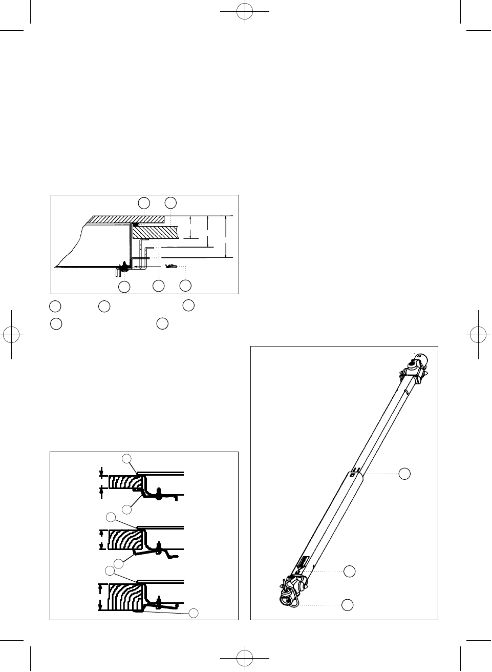
these hobs must be carried out in the way
shown in the drawing 14, depending on the
thickness of the work top.
Seal Work top Screw
Fastening clip Quick-fix nut
CGC 4G
Once the hob position has been dimensioned,
the seal must be affixed (J) to the hob.
Fix the clamps (K) into the holes on the lower
p a rt of the case, as shown in drawing, by tighte-
ning the four screws supplied (ø4.2 mm).
The clamps (K) and seal (J) are supplied in the
packaging along with the hob. (See drawing 15).
If the unit below the hob is to be used to store
p r oducts it must be situated at a distance of at
least 10 cm below the hob. Furt h e rm o re, it must
be taken into account that the temperature in the
interior of the furn i t u re may rise to 60
o
C .
CONNECTING THE HOB TO THE OVEN
(Mod. CG.1 4G, CG.1 3G 1P and CGC 4G) OR
THE CONTROL PANEL
To connect the hob to the oven, four telescopic
universal joints are provided. (See drawing 16).
To make this connection, proceed as follows:
1 Disconnect from the mains supply (mod.
CG.1 3G 1P and CGC 4G AI AL).
2 Detach the telescopic universal joints by
p ressing the retention tab (marked PUSH)
using a thin screwdriver and extract the
extender a few centimetres.
11
20
J
30
40
J
J
K
K
K
Drawing 15
A
C
D
E
B
A
B
C
D
E
20 mm.
30 mm.
40 mm.
Drawing 14
A
A
B
Drawing 16
61401134/329 ingles 18/7/03 16:55 Página 11


