Before connecting the hob to the power supply
check that the voltage and frequency are tho-
se indicated in the rating plate located on the
lower part of the hob.
Remove the protecting plastic affixed to the
hob, if any.
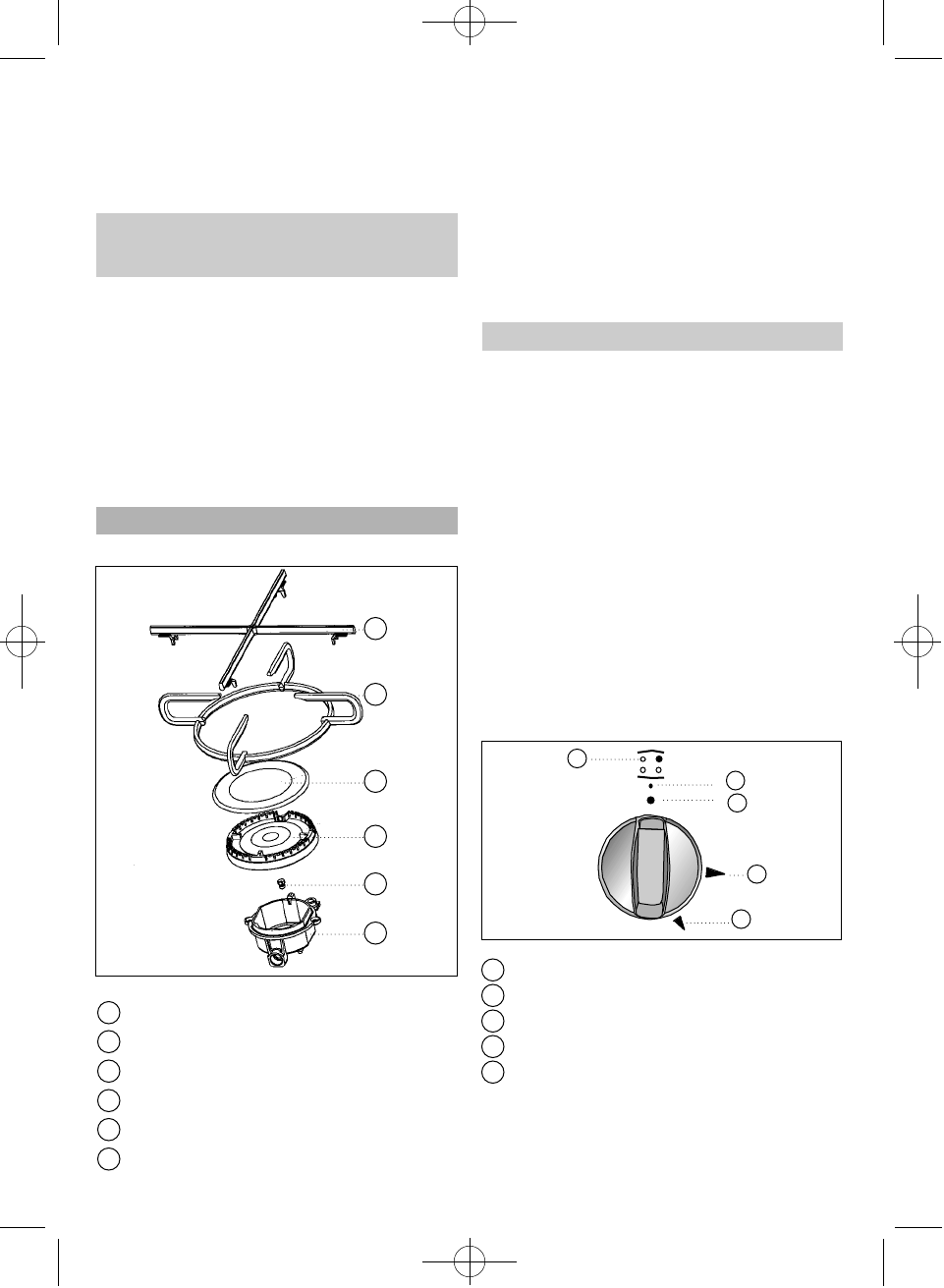
Pan support supplement
Pan support
Burner cover
Burner head
Gas nozzle
Nozzle unit
N.B. Each time you assemble a burner, check
that all of its component parts fit together
c o rre c t l y. A badly positioned component may
cause the hob glass to overheat.
For hobs models CGC 4G, CG.1 4G. and CG.1
3G. 1P. (See drawing 20).
• Check that the controls are in the corre c t
position.
• Open the mains connection gas tap or the
gas bottle cock.
• Put a lit match, lighter or flame, etc. next
to the burner if no automatic lighting is
available.
• While keeping the burner control pre s s e d ,
t u rn it in anti-clockwise direction as far as it
will go until the maximum setting (large flame
“C”). The burner operates at that moment at
full power. Then, if desired, turn the control to
the minimum position (small flame “D”).
Burner indicator
Setting indicator
Off setting
Minimum gas setting
Maximum gas setting
For hobs CG Lux-60, CG Lux-70, CG Lux-75
and CG Lux-86, which have automatic igni-
tion and a safety feature, the following steps
should be followed: (See drawing21).
24
Use and Maintenance
Special requirements
before first use
Component Parts of Gas Burners
C
A
B
D
E
F
A
B
C
D
E
F
Drawing 19
Ligthing of Burners
A
B
C
E
D
Drawing 20
A
B
C
D
E
61401134/329 ingles 18/7/03 16:57 Página 24


