3 Remove the four lockpins from the ends (B).
4 P a rtially insert the oven in its position, taking
c a re not to snag the telescopic universal
joints which are hanging from the underside
of the hob, and leave sufficient space to be
able to connect the other ends of the joints
to the rods at the rear part of the contro l
panel, before finally connecting the lockpins.
5 For the electrical connection between the
two appliances, connect the hob connector
to the oven connector (mod. CG.1 3G 1P
and CGC 4G AI AL).
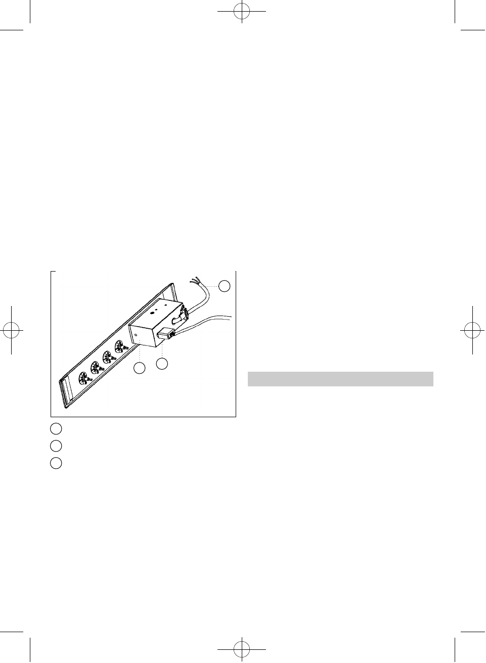
Rear view of the Control Panel:
Flexible Power Cable.
Connector.
Power Unit Protective Casing.
6 Position the oven in its definitive location,
ensuring that the telescopic universal
joints are well connected to the rods and
that the telescopic tubes are intro d u c e d
well aligned with each other in order to
favour their movement.
7 Position the control panel on the oven’s
fascia.
8 To operate, the controls must be pre s s e d
in and then turned in order to release the
safety device.
If the telescopic universal joints are too short,
extensions can be used. These are inserted at
pressure and fastened with the corresponding
cover.
To make the oven’s electrical connection, con-
sult the oven’s instruction manual.
Hob model CGC 4G AI AL
This hob should be fitted onto the oven by
following the same method, except for item 7,
where the procedure shall be as follows:
Fix the hob knob covers on the oven according
to the oven instructions manual. Fix the knob
covers included with the hob and remove tho-
se for the oven.
This hob comes complete with knob covers for
all TEKA ovens except for models RT-600 and
RT-800. For these two models, order the knob
covers in your nearest TEKA establishment or
official technical service.
The hob’s gas connection to the mains supply
must be made in accordance with the applica-
ble installation regulations and by qualified
technical personnel (an authorized installer).
The gas connection for these hobs must be by
means of rigid piping, given that this is an
immobilized appliance, in the case of hobs
destined for the EC. The hob is pre p a red with
a
1
/2"
diameter screw connection according to
ISO 228-1, or
1
/2"
diameter conical screw con-
nection to ISO 7-1 according to the regulations
of the receiving country.
For the markets with
1
/2"
ISO 228-1 connec-
tion a copper tube of diameter 10/12 mm is
suplied as an accessory. This can be welded
to the gas intake pipe.
The room must be provided with adequate ven-
tilation, in accordance with the applicable
regulations.
12
1
2
3
Drawing 17
1
2
3
Gas Connection
61401134/329 ingles 18/7/03 16:55 Página 12


