5
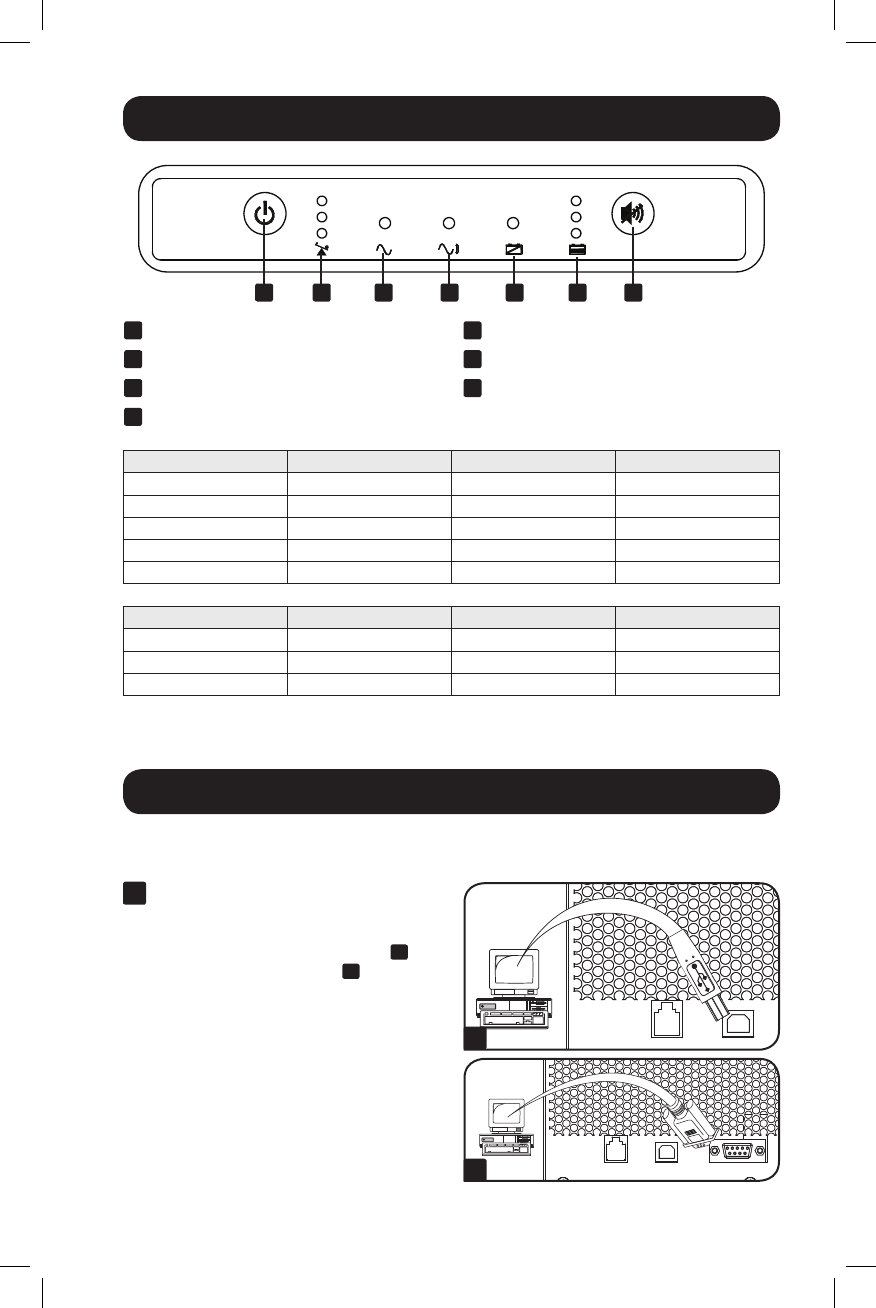
User Interface
A
On/Off/StandbyButton
B
OutputLoadLevelLEDs
C
Power LED
D
Voltage Correction LED
Optional Installation
These connections are optional. Your UPS will function properly without these
connections.
1
USB and RS-232 Serial
Communications
UsetheincludedUSBcable(see
1a
)
andDB9serialcable(see
1b
) to
connect the communication port on your
computer to the communication port of
your UPS. Install the Tripp Lite
PowerAlert Software appropriate to your
computer’s operating system.
Load Level States LED Indicator Audible Alarm
0-75% Line, Invert Green —
76-100% Line, Invert Yellow —
101-110% Line, Invert BlinkingRed —
>110% Line Red —
>110% Invert Red On
Runtime Condition States LED Indicator Audible Alarm
>3minremaining Invert Green —
3-2minremaining Invert Yellow —
<2 min remaining Invert Red On
E
BatteryWarningLEDs
F
BatteryChargeLEDs
G
Mute/TestButton
A B C D E F G
1a
1b
12-10-307-93-3181.indb 5 11/2/2012 9:27:43 AM


