1. Turn on Input breaker on the rear panel after checking the power wiring. The cooling fans should be
rotating and the control panel should show the display as below.
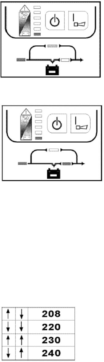
Fig 1.1-1 Bypass Mode (Load LED display depends of load level)
2. Then press the “|” button. After 10 seconds, the control panel will become what is shown in Fig. 1.2-1.
3. Turn on the output breaker located on the rear panel to provide power to the load.
Fig 1.2-1 Inverter Mode
4. The UPS should be successfully started.
5. If the UPS is in normal operation, the user can run a battery-mode test by pushing the “ON” button. The
four LED’s on the lower half of the control panel (i.e. line, bypass, battery, inverter) will flash.
6. To turn off the UPS, push the “OFF” button, then turn off the line breaker.
2. OUTPUT VOLTAGE SETTING
Four voltage options are available (208V, 220V, 230V, 240V). Users can set the desired voltage through DIP
SWITCHES located on the rear panel. The output voltage can be switched according to the instructions below.
1. Press the “OFF “ button to turn off the UPS.
2. Switch the output breaker to the OFF position.
3. Turn off Input breaker.
4. Wait until the fans stop turning, then switch the DIP SWITCHES to the desired voltage position. Table 2-1,
also printed under DIP SWITCHES, shows these four positions and their corresponding voltage levels.
5. After setting the switches, turn on the Input breaker, press the “| “ button and then turn on the output
breaker.
NOTE: On units with an isolation transformer, the secondary voltage will be 1/2 of the DIP SWITCH setting.
The voltage setting has been successfully changed when the UPS switches to INVERTER mode.
Table 2-1
Page A1
3. DISPLAYS AND ALARMS
1. Load level and battery capacity is represented by 5 LEDs on the upper half of control panel (the 6th LED means
FAULT).


