(A). When the UPS is in on-line mode, the 5 LEDs represent load level. They denote 0%~35%, 35%~55%,
55%~75%, 75%~95% and 95%~105% (from bottom to top) of maximum load capacity. If the load amount
reaches 105%~130%, the UPS is in overload such that the 6 LEDs would illuminate simultaneously. The
UPS will then switch to BYPASS mode 10 seconds later. In addition, if the load is over 130%, the UPS will
switch to BYPASS immediately.
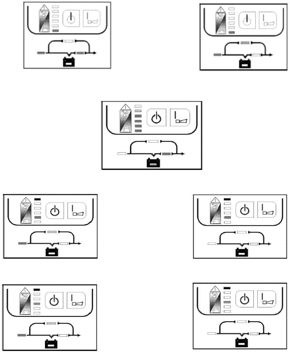
Fig 3.1-1 Inverter Mode Fig 3.1-2 Bypass Mode
(B). During an AC line power failure, these 5 LEDs represent the remaining battery capacity. The LED’s will
extinguish by the sequence from bottom to top as the battery voltage level decreases.
Fig 3.1-3 Battery Mode
2. An alarm will sound continuously during inverter short-circuiting or an output over voltage condition.
Fig 3.2-1 Line Mode Fig 3.2-2 Battery Mode
3. An alarm will sound continuously during a bus over voltage condition.
Fig 3.3-1 Line Mode Fig 3.3-2 Battery Mode
Page A2
4. An alarm sounds continuously during an over-temperature condition.


