1800IF - PAGE 8 OF 19
Valvcon Corporation
http://www.valvcon.com
phone: 603-249-9020 fax: 603-249-9140
2. O
PERATING
P
ROCEDURES
2.1 O
PEN
/
CLOSE UNITS
(
NO BOARD OPTIONS INSTALLED
)
These units must be powered in each direction. That is, to drive in the clockwise direction, power must be applied
to terminals 1 and 4; to drive in the counter-clockwise direction, power must be applied to terminals 1 and 3. The
actuator will continue to rotate in the appropriate direction until power is removed or a cam trips an end-of-travel
limit switch. Once the actuator reaches an end-of-travel switch, power may be removed or may remain applied
without damaging the actuator.
For AC powered units, if power is still applied to terminals 3 or 4 after the actuator reaches the end of travel, that
power is routed back to terminals 5 and 6 (respectively). This power may be used for end-of-travel indication.
Wiring for Open/Close units with no board options installed, and for each of the options listed below, is provided
on the following pages.
2.1.1 HEATER AND THERMOSTAT OPTION (ORDER CODE "T")
The heater and thermostat option is used to maintain the appropriate internal ambient temperature, and also to
assist in eliminating internal condensation in environments that experience wide temperature swings. It should be
used in environments in which the temperature may potentially drop below 40 degrees F, and/or in environments
which experience wide temperature swings.
The heater strip is energized whenever the ambient temperature drops below 40 degrees F. and remains
energized until the ambient temperature exceeds 60 degrees F. Valvcon uses a 15-Watt heater for 115VAC,
24VAC, 12 VDC and 24VDC units, and a 40-Watt heater for 230VAC units.
To power the heater and thermostat, power must be constantly applied to terminals 1 and 2.
For Cycle Rate
Regulator boards see page 12 for specific instructions.
For high humidity or "tropical" environments, Valvcon offers the "tropical heater and thermostat" package.
Consult your local Valvcon stocking representative for details.
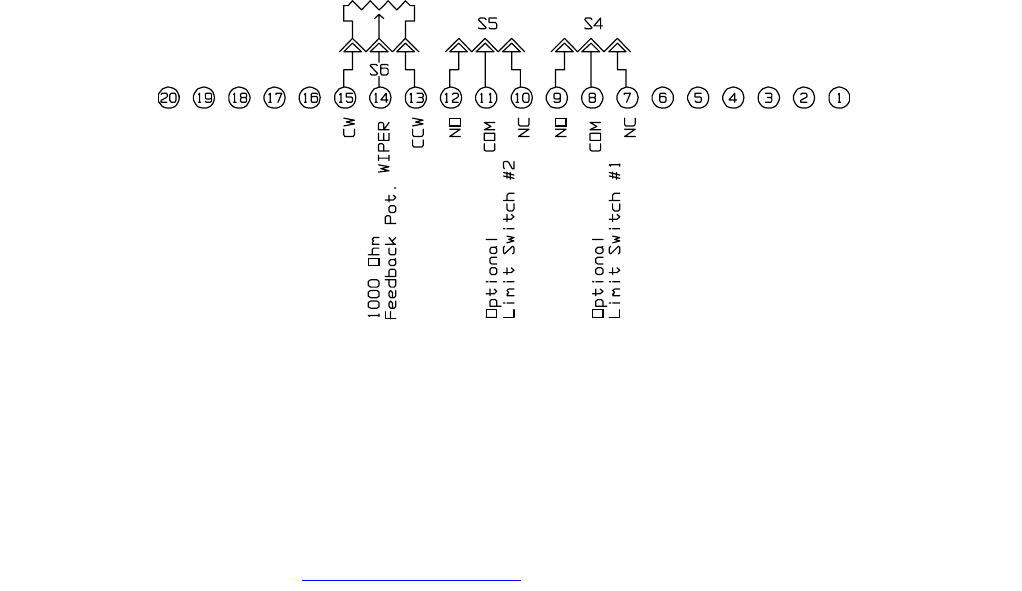
2.1.2 FEEDBACK POTENTIOMETER OPTION (ORDER CODE "P")
The Feedback Potentiometer provides a variable resistance (0-1000 ohms) to indicate the position of the
actuator's output shaft. The signal can be fed at positions 13, 14 and 15 on the terminal strip.
WIRING
Potentiometer Wiring