6 7
STEP 3. Remove backing from gasket. Attach
adhesive side to base plate. IF YOU ARE
USING THE ROOF WEDGE (RW-5000), use
3/16” gasket included with the mount UNDER
the roof wedge. Install the 1/16” gasket
included with
RW-5000 BETWEEN the mount
and roof wedge.See Figure 7.
The word FRONT is
embossed on the base. This MUST
FACE the front of the vehicle.
Secure to roof using two mounting
screws provided. Check inside the vehicle.
Be sure the shaft is centered in the hole.
Attach crank handle to shaft.
Crank unit up until it stops.
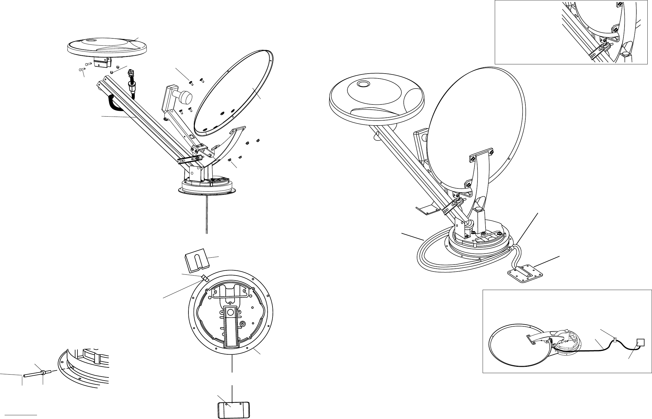
STEP 4. Attach reector to backup assembly, Figure 6.
STEP 5. Attach RS-1000 antenna to elevating tubes.
Use the two E-clips and pins provided, Figure 6. Attach
coax cable to F-jack on antenna and slide on weather
boot, Figure 6.
STEP 6. Install remaining mount base screws. Install
the vent tube on the back of the mount base. (This is the
side opposite the word FRONT.) The hole for the vent
tube is shown in Figure 8.
CAUTION: DO NOT seal hole in vent tube. Put sealant
around the outside of the vent tube, approximately 1/2”
from end, Figure 8. Push the vent tube into the hole. The
sealant will seal the hole as you push in. Leave approxi-
mately 2 to 2-1/2” of the vent tube extending from the
hole. Put a small amount of approved sealant on the roof
and under the vent tube to hold in place.
STEP 7. Facing the front of the dish, nd coax cables
attached to side of the feed arm, Figure 9. Measure 24”
of coax from this point and mark. DO NOT CUT. Rotate
mount on base clockwise, fully, until it stops. Route coax
around mount base, Figure 10.
Fasten cable clamp in hole in mount base (check roof
template inserted in this manual for correct location) at
end of the coax cable measurement.
STEP 8. Feed coax cables through the roof. Weather-
proof cable entry by applying sealant under the lip of
the cable-entry plate and where cable enters roof. Attach
plate to roof with screws provided. Apply sealant over
screws and around edge of roof-through plate, making
sure cable entry is sealed. Secure cables as necessary
to prevent whipping. If cable connections are exposed,
be sure to weatherproof connection!
Mount travel bracket to roof 6-1/8” from base, Figure
7, page 6.
STEP 9. Apply approved sealing compound to screw
heads, cable entrance hole and edge of gasket under
mount, AFTER mounting, Figure 7.
STEP 10. Attach satellite coax cable (with RG-6 printed
on it) to the satellite receiver.
STEP 11. Attach RS-1000 coax downlead (with RG-59
printed on it) to RV-7542 power supply. Refer to power
supply instruction sheet. You can connect the antenna
FIGURE 6
FIGURE 8
FIGURE 7
FIGURE 9
Measure coax
24” from plastic tie
wrap on left side of
feed arm. (STEP 7)
FIGURE 10
Cable-entry plate
Minimum 3” from
mount base
Cable
clamp
Do not attach
cable clamp
with screw
to base plate
until installing
cable.
Base plate
6-1/8”
Travel Bracket
output from the power spply directly to the “TV ANT IN” on
satellite receiver. (Refer to receiver manual.) This allows
you to watch local channels when you turn off the receiver.
STEP 12. Connect digital elevation sensor at roof level, see
top of page 8.
ANOTHER METHOD OF INSTALLING ROOF CABLE/
ENTRY PLATE: Attach cable to roof using cable clamp.
Use sealant to seal screw heads.
Attach RS-1000 to
ELEVATING TUBES using
E-Clips and Pins supplied.
PINS
E-CLIPS
RS-1000 ANTENNA
REFLECTOR
(4) ANTENNA
MOUNTING BOLTS
(4) 1/4 - 20
HEX NUT
DO NOT CLAMP THIS SECTION
OF CABLE. Must be free to
move when rotating unit.
Attach coax
cable clamp at
screw hole on
front of mount
base.
Cable entry plate
placement is 3”
MINIMUM from
mount base.
3” MINIMUM
from mount
base.
FRONT
CAUTION: DO NOT GET sealing compound between
base plate and Rotating Gear Housing.
Vent Tube
Sealant
2-2½”
Cable Clamp
Cable entry plate
Cable


