


C
Copyright © 2001. Nokia Mobile Phones. All rights reserved.
Nokia 6090 technical information 12
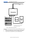
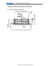
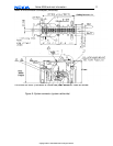
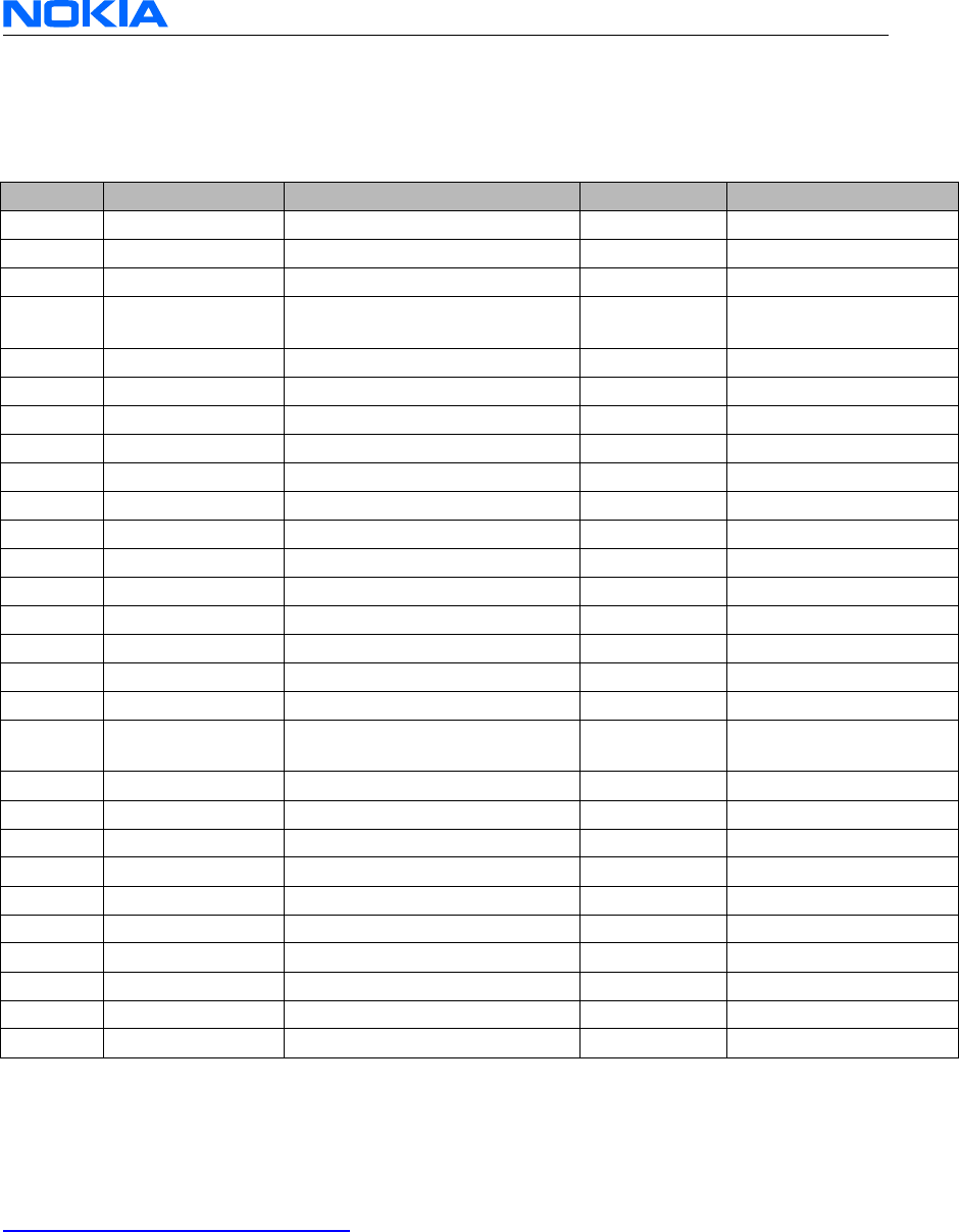
7.2 System connector pinning
The following table consists of the pin out of the system connector. The connections on
the system connector are shown in the following table, I/O's are given in view from the
radio unit (transceiver).
Pin No. Name Function Direction Type
1 CARBAT+ Battery Plus Input Power (10.8V.16V)
2 CARBAT- Battery Minus Input Power (0V)
3 BLD Back light dimming Input PWM 12V
4 AMC Antenna-Motor Control Output Open collector (active
high)
5,6 N.C.
7 to Handset
8 to Handset
9 to Handset
10 to Handset
11 SHIELD Line out Shield for Lineout Output Power/Analog
12 N.C.
13 LineOutP Line Output (pos.) Output Analog
14 LineOutN Line Output (neg.) Output Analog
15, 16 N.C.
17 CARBAT+ Battery Plus Input Power (10.8V.16V)
18 CARBAT- Battery Minus Input Power (0V)
19 IGS Ignition Sense Input Dig. 12V
20 CRM Car-Radio Mute Output Open Collector (active
low)
21, 22 N.C.
23 to Handset
24 to Handset
25 to Handset
26 to Handset
27 HFMICGND handsfree Microphone GND Output Power/Analog
28 HFMICP handsfree Microphone +8V/In I/O Analog
29, 30 N.C.
31 HFSPKN handsfree loudspeaker (neg.) Output Analog
32 HFSPKP handsfree loudspeaker (pos.) Output Analog
Figure 9: Pinning of the system connector
8 Additional information
Additional information is confidential but may be available upon application per e-mail to:
6090.productsupport@nokia.com
Please mention company, web site address, your full name, full postal address, the kind
of application the development is for and other details you may find useful for us to know
about.
Technical questions related to the Nokia 6090 can be sent to above-mentioned address.