


C
Copyright © 2001. Nokia Mobile Phones. All rights reserved.
Nokia 6090 technical information 9
6 Data connector description and pinning
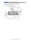
6.1 Data connector description
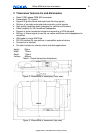
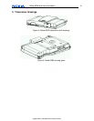
Figure 6: Nokia 6090 integrated data connector (front view)
Name of the connector counterpart (wire side): D-SUB 9
Possible names of the connector counterpart cable: standard modem cable, extension
cable for modem/mouse/monitor, DB9-DB9 cable, female-male 9 pin serial cable.
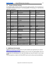
6.2 Data connector pinning
The following table describes pin-out of the data connector:
Pin /
Connector
Line Symbol
Minimum Typical /
Nominal
Maximum Unit / Notes
1
RS-232 DCD
Handshake: Data
Carrier Detect
(output)
+/- 3,3 +/-5,4 +/- 15 V/ inactive
V /active
2
RS-232 RD
Received Data (output)
+/- 3,3 +/-5,4 +/-15 V / binary state 1
V / binary state 0
3
RS-232 TD
Transmitted data
(input)
- 1,2 / 1,5 - V/ binary state 1
V/ binary state 0
4
RS-232
DTR
(input)
- 1,2 / 1,5 - V / inactive
V / active
5
GND
(Power Supply)
0 V/ reference ground
6
RS-232
DSR
(output)
+/- 3,3 +/-5,4 +/- 15 V / inactive
V/ active
7
RS-232
RTS
(input)
- 1,2 / 1,5 -
V / inactive
V/ active
8
RS-232
CTS
(output)
+/- 3,3 +/-5,4 +/- 15 V / inactive
V/ active
9
RI
(output)
+/- 3,3 +/-5,4 +/- 15 V / inactive
V/ active
Table 3: Pinning of the data connector (RS-232 Interface)