


LBI-38965
A-3
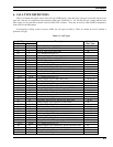
5. RECORD LAYOUT
5.1. SINGLE-SITE CALLS
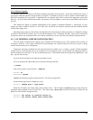
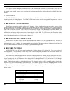
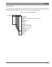
The following diagram shows the layout of the fields in a basic CDR for a single-site call. The top row shows the field
name and number, the middle row shows the subfield name and letter, if applicable, and the bottom row shows the byte offset
within the record.
1. Record
Type
2. Node ID No. 3. Record ID No. 4. Start Date 5. Start Time
a. System b. Node a. Year b. Month c. Day a. Hour b. Minute c. Second
01234567891011121314151617181920212223
6. Call
Type
7. Caller ID No. 8. Callee ID No.
24 25 26 27 28 29 30 31 32 33 34 35 36 37 38 39 40 41 42 43 44 45
9. Elapsed Time 10. Accumulated Air Time 11. No. of Channel
Assignments
12. No. of
Sites
13. Site of Origin
a. No. b. Channel Map
46 47 48 49 50 51 52 53 54 55 56 57 58 59 60 61 62 63 64 65 66 67 68 69
Figure A.1 - Call Detail Record, Single-Site Call
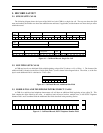
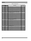
5.2. MULTIPLE-SITE CALLS
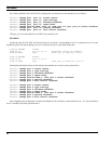
A CDR may have 0 to n additional fields added beginning at byte offset 70, where n = No. of Sites - 1. The format of the
additional fields is identical to the Site of Origin field (field 13) and is shown in the diagram below. The offset, x, of the first
byte in each additional field is calculated as x = 62 + (8n).
Figure A.2 - Call Detail Record, Additional Site Field
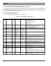
5.3. MOBILE-TO-LAND TELEPHONE INTERCONNECT CALLS
A CDR for a mobile-to-land telephone interconnect call will have an additional field beginning at byte offset 70. This
field contains the digits dialed by the caller. A mobile-to-land call never involves multiple sites, so the PSTN Telephone
Number field is never combined with the Additional Site fields described in the preceding section.
14. PSTN Telephone No.
70 71 72 73 74 75 76 77 78 79 80 81 82 83 84 85 86 87 88 89 90 91
..
101
Figure A.3 - Call Detail Record, PSTN Telephone Number Field
13 +n. Additional Site n
a. No. b. Channel Map
x x+1 x+2 x+3 x+4 x+5 x+6 x+7