


LBI-38965
A-4
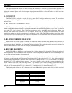
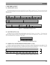
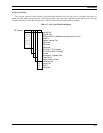
5.4. CALCULATING THE NUMBER OF BYTES IN A CDR
Note that the final linefeed character which terminates the record is not shown in these diagrams. The actual number of
bytes in a CDR is calculated by adding 2 to the offset of the final byte. For example, a group call involving 4 sites contains 3
additional site fields, beginning at offset 70 and ending at offset 93 (from the formulae above). The actual length of the
record, including the linefeed character, is thus 95 bytes.
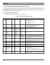
5.5. CDR FIELD DESCRIPTIONS
Table A.1 contains detailed descriptions of each of the CDR fields.
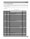
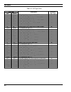
Table A.1 - Call Detail Record Field Descriptions
No. Name Size Format Range/Values Description
1. Record Type 2 Hex 00 - FF Defines the type of record.
00 = Mobile to Mobile
01 = Mobile to Land Interconnect
02 = Illegal
03 = Land to Mobile Interconnect
04 = Data
05- FF = Reserved
2.
a.
b.
Node ID No.
System
Node
4
2
2
Hex
Hex
00 - FF
00 - FF
Unique identification number for the EDACS node where the call
activity in this CDR occurred. User configurable.
System ID Number (Multiple nodes)
Node ID Number (Multiple sites)
3. Record ID No. 4 Radix-64 Unique identifier for the Call Detail Record.
4.
a.
b.
c.
Start Date
Year
Month
Day
8
4
2
2
Decimal
Decimal
Decimal
1970-2038
01 - 12
01 - 31
The date when the call was initiated.
5.
a.
b.
c.
Start Time
Hour
Minute
Second
6
2
2
2
Decimal
Decimal
Decimal
00 - 23
00 - 59
00 - 59
The time of day when the call was initiated. Hours are in military
format.
6. Call Type 2 Hex 00 - FF (See
Table A.2)
The type of call as defined in Table A.2. Indicates whether call is
group or individual, whether to bill the caller or the callee, etc.
7. Caller ID No. 10 Decimal 0000000000 -
9999999999
For Record Types 00 and 01, this field contains the Logical ID (LID)
of the caller. For Record Type 03, the field contains the
Interconnect Line number.
8. Callee ID No. 10 Decimal 0000000000 -
9999999999
For Record Types 00 and 03, this field contains the Logical ID (LID)
of an individual callee, or the Group ID (GID) of a call group. (The
Call Type field indicates individual or group call.) For Record Type
01, the field contains the Interconnect Line number.
9. Elapsed Time 4 Hex 0000 - FFFF The duration of the call in seconds
10. Accumulated Air
Time
5 Hex 00000 - FFFFF The number of seconds of actual air time used on all sites on the
local node for this call. Does not include air time on site 32 which is
a remote node.
11. No. of Channel
Assignments
5 Hex 00000 - FFFFF The number of times a channel assignment occurred on a site within
the local node for this call.
12. Number of Sites 2 Decimal 01 - 32 The number of sites on the local node which participated in this call.
13.
13+n
a.
b.
Site of Origin /
Additional Site n
Site Number
Channel Map
8
2
6
Decimal
Hex
01 - 32
000000 - FFFFFF
Information on the site of Origin (field 13) and any additional sites
participating in the call.
Site number (site 32 represents a remote node).
A hexadecimal bitmap, where bit 0 = channel 1. A bit value of 1
indicates at least one channel assignment on the indicated
channel.
14. PSTN Telephone
No.
32 Dialed Digits Occurs in Record Type 01 only. Contains up to 32 digits dialed by
the caller. The digits are left justified and padded with ASCII SP
(decimal 32) on the right.